Dunbar Gardens Elevated Courtyard Walkway Renovations Specifications
HAKC Housing Authority of Kansas City, Missouri
Project Manual for Dunbar Gardens

Elevated Courtyard Walkways Renovation
August 2024
Davidson & Associates, Inc.
Architecture, Engineering, Planning, Design/Build, Energy & Construction Management
Issued for Bid Set
Dunbar Gardens Elevated Walkways Renovation
Table of Contents
Click the links below to jump to each section
- Division 00:- Procurement and Contracting Requirements
- Refer to HAKC Documents
- Refer to HAKC Documents
- Division 01: - General Requirements
- Section 01 11 00 - Summary of Work
- Section 01 32 00 - Construction Progress Documentation
- Section 01 33 00 - Submittal Procedures
- Section 01 73 10 - Cutting and Patching
- Section 01 73 20 - Selective Demolition
- Section 01 77 00 - Closeout Procedures
- Division 03: - Concrete
- Section 03 30 00 - Cast In Place Concrete
- Section 03 30 00 - Cast In Place Concrete
- Division 05: - Metals
- Section 05 12 00 - Structural Steel
- Section 05 31 00 - Metal Deck
- Section 05 73 00 - Decorative Metal Railings
- Appendix-A-Photos-of-Existing-Conditions
- Photos of Existing conditions
Division 01: - General Requirements
Section 01 10 00 - Summary of Work
Part 1 General
1.1 Related Documents
- Drawings and general provisions of the Contract, including General and Supplementary Conditions and other Division 01 Specification Sections, apply to this Section.
1.2 Work Covered by Contract Documents
- The Project consists of interior modernization of the top three (3) floors of the twelve-story tower as part of phase one. General scope of work included but not limited to demolition and new work for new elevated exterior walkways.
- Project Loc. on:
- 3992 Colorado Ave. Kansas City, Missouri 64124
- 3992 Colorado Ave. Kansas City, Missouri 64124
- Owner: Housing Authority of Kansas City, Missouri (HAKC), 3822 Summit St. Kansas City, Kansas 64111.
- Project Loc. on:
- Contract Documents, dated August 2024 were prepared for the Project by Davidson & Associates, Inc.
- The Work will be constructed under a single prime contract.
1.3 Contractor Use of Premises
- General: During the construction period the Contractor shall have partial use of the premises for construction operations, including use of the site as agreed upon with the Owner. The Contractor shall maintain safe egress to each apartment from corridor to apartment as well as exterior egress and security. All work in an area affecting apartments, public areas and exterior shall be demolished completed and cleanup for residence use the following day. The contractor shall submit a phasing plan indicating work schedule to be approved by the HAKC at the time of contract negotiation.
- Use of the Site: Limit use of the premises to work in areas indicated on approved phasing plan. Any deviation from the plan will not be allowed unless authorized by HAKC staff in writing two weeks prior to variance in work required. Confine operations to areas within contract limits indicated. Do not disturb portions of the site beyond the areas in which the Work is indicated.
- Owner Occupancy: Allow for Owner occupancy and use by the public.
- Driveways and Entrances: Keep driveways and entrances serving the premises clear and available to the Owner, the Owner's employees, and emergency vehicles at all times. Do not use these areas for parking or storage of materials. Schedule deliveries to minimize space and time requirements for storage of materials and equipment on-site.
- Owner Occupancy: Allow for Owner occupancy and use by the public.
- Use of the Existing Buildings: Maintain the existing buildings in a weather tight condition throughout the construction period. Repair damage caused by construction operations. Take all precautions necessary to protect the building and its occupants during the construction period.
1.4 Occupancy Requirements
- Full Owner Occupancy: The Owner and its tenants will occupy the site and existing building during the entire construction period. Cooperate with the Owner during construction operations to minimize conflicts and facilitate owner usage. Perform the Work so as not to interfere with the Owner's operations.
Part 2 - Products (Not Applicable)
Part 3 - Execution (Not Applicable)
End of Section 01 10 00
Section 01 32 00 - Construction Progress Documentation
Part 1 - General
1.1 Related Documents
- Drawings and general provisions of the Contract, including General and Supplementary Conditions and other Division 01 Specification Sections, apply to this Section.
1.2 Summary
- This Section includes administrative and procedural requirements for documenting the progress of construction during performance of the Work, including the following:
- Contractors Construction Schedule
- Submittals Schedule
1.3 Definitions
- Activity: A discrete part of a project that can be identified for planning, scheduling, monitoring, and controlling the construction project. Activities included in a construction schedule consume time and resources.
- Critical activities are activities on the critical path. They must start and finish on the planned early start and finish times.
- Predecessor activity is an activity that must be completed before a given activity can be started.
- CPM: Critical path method, which is a method of planning and scheduling a construction project where activities are arranged based on activity relationships. Network calculations determine when activities can be performed and the critical path of a Project.
- Critical Path: The longest continuous chain of activities through the network schedule that establishes the minimum overall Project duration and contains no float.
- Event: The starting or ending point of an activity
- Float: The measure of leeway in starting and completing an activity
- Float time is not for the exclusive use or benefit of either Owner, but is a jointly owned, expiring Project resource available to both parties as needed to meet schedule milestones and Contract completion date.
- Free float is the amount of time an activity can be delayed without adversely affecting the early start of the following activity.
- Total float is the measure of leeway in starting or completing an activity without adversely affecting the planned Project completion date.
- Fragnet: A partial or fragmentary network that breaks down activities into smaller activities for greater detail.
- Major Area: A story of construction, a separate building, or a similar significant construction element.
- Milestone: A key or critical point in time for reference or measurement.
- Network Diagram: A graphic diagram of a network schedule, showing activities and activity relationships
1.4 Submittals
- Submittal Schedule: Submit four copies of the schedule. Arrange the following information in a tabular format:
- Scheduled date for first submittal
- Specification Section number and title.
- Submittal category (action or informational).
- Name of subcontractor.
- Description of the Work covered.
- Scheduled date for Architect's final release or approval.
- Construction Schedule: Submit four printed copies; one a single sheet of reproducible media, and one a print, beyond HUD required Construction Progress Schedule.
- Submit an electronic copy via email to KCKHA modernization department and Architect, using Microsoft Project, and labeled to comply with requirements for submittals. Include type of schedule (Initial or Updated) and date on label.
1.5 Coordination
- Coordinate preparation and processing of schedules and reports with performance of construction activities and with scheduling and reporting of separate contractors.
- Coordinate Contractor's Construction Schedule with the Schedule of Values, list of subcontracts, Submittals Schedule, progress reports, payment requests, and other required schedules and reports.
- Secure time commitments for performing critical elements of the Work from parties involved.
- Coordinate each construction activity in the network with other activities and schedule them in proper sequence.
- Auxiliary Services: Cooperate with photographer and provide auxiliary services requested, including access to Project site and use of temporary facilities including temporary lighting.
Part 2 - Products
2.1 Submittals Schedule
- Preparation: Submit a schedule of submittals, arranged in chronological order by dates required by construction schedule. Include time required for review, resubmittal, ordering, manufacturing, fabrication, and delivery when establishing dates.
- Coordinate Submittals Schedule with list of subcontracts, the Schedule of Values, and Contractor's Construction Schedule.
- Initial Submittal: Submit concurrently with bar-chart schedule. List those required to maintain orderly progress of the Work and those required early because of long lead time for manufacture or fabrication.
- Show submittals on the Construction Schedule, instead of tabulating them separately.
2.2 Contractor's Construction Schedule, General
- Procedures: Scheduling: Comply with procedures contained in AGC's "Construction Planning & Scheduling
- Time Frame: Extend schedule from date established from the Notice to Proceed to date of Substantial Completion.
- Contract completion date shall not be changed by submission of a schedule that shows an early completion date, unless specifically authorized by Change Order.
- Contract completion date shall not be changed by submission of a schedule that shows an early completion date, unless specifically authorized by Change Order.
- Activities: Treat each story or separate area as a separate numbered activity for each principal element of the Work. Comply with the following:
- Submittal Review Time: Include review and resubmittal times indicated in Division 1 Section "Submittal Procedures" in schedule. Coordinate submittal review times in Contractor's Construction Schedule with Submittals Schedule.
- Startup and Testing Time: Include days for startup and testing.
- Substantial Completion: Indicate completion in advance of date established for Substantial Completion and allow time for Architect's administrative procedures necessary for certification of Substantial Completion.
- Constraints: Include constraints and work restrictions indicated in the Contract Documents and as follows in schedule and show how the sequence of the Work is affected.
- Phasing: Arrange list of activities on schedule by phase.
- Work Restrictions: Show the effect of the following items on the schedule:
- Coordination with existing.
- Limitations of continued occupancies.
- Uninterruptible services.
- Use of premises restrictions.
- Provisions for future construction.
- Seasonal variations.
- Environmental control.
- Work Stages: Indicate important stages of construction for each major portion of the Work, including, but not limited to, the following:
- Subcontract awards.
- Submittals.
- Purchases.
- Fabrication.
- Sample testing.
- Deliveries.
- Installation.
- Tests and inspections.
- Adjusting.
- Startup and placement into final use and operation
- Area Separations: Identify each major area of construction for each major portion of the Work. Indicate where each construction activity within a major area must be sequenced or integrated with other construction activities.
- Milestones: Include milestones indicated, including, but not limited to, the Notice to Proceed, Substantial Completion, and Final Completion of each facility.
- Cost Correlation: At the head of schedule, provide a cost correlation line, indicating planned and actual costs. On the line, show dollar volume of the Work performed as of dates used for preparation of payment requests.
- Contract Modifications: For each proposed contract modification concurrent with its submission, prepare a time-impact analysis using fragnets to demonstrate the effect of the proposed change on the overall project schedule.
2.3 Contractor's Construction Schedule (CPM Schedule)
- General: Prepare network diagrams using AON (activity-on-node) format.
- CPM Schedule: Prepare Contractor's Construction Schedule using a CPM network analysis diagram.
- Develop network diagram in sufficient time to submit CPM schedule so it can be accepted for use no later than 5 business days after date established for the Notice of Award.
- Conduct educational workshops to train and inform key Project personnel, including subcontractors' personnel, in proper methods of providing data and using CPM schedule information.
- Establish procedures for monitoring and updating CPM schedule and for reporting progress. Coordinate procedures with progress meeting and payment request dates.
- Use "one workday" as the unit of time.
- CPM Schedule Preparation: Prepare a list of all activities required to complete the Work. Using the preliminary network diagram, prepare a skeleton network to identify probable critical paths.
- Activities: Indicate the estimated time duration, sequence requirements, and relationship of each activity in relation to other activities. Include estimated time frames for the following activities:
- Preparation and processing of submittals.
- Purchase of materials.
- Delivery.
- Fabrication.
- Installation.
- Processing: Process data to produce output data or a computer-drawn, time-scaled network. Revise data, reorganize activity sequences, and reproduce as often as necessary to produce the CPM schedule within the limitations of the Contract Time.
- Format: Mark the critical path. Locate the critical path near the center of network; locate paths with most float near the edges.
- Subnetworks on separate sheets are permissible for activities clearly off the critical path
- Subnetworks on separate sheets are permissible for activities clearly off the critical path
- Activities: Indicate the estimated time duration, sequence requirements, and relationship of each activity in relation to other activities. Include estimated time frames for the following activities:
- Initial Issue of Schedule: Prepare initial network diagram from a list of straight "early start-total float" sort. Identify critical activities. Prepare tabulated reports showing the following:
- Contractor or subcontractor and the Work or activity.
- Description of activity.
- Principal events of activity.
- Immediate preceding and succeeding activities.
- Early and late start dates.
- Early and late finish dates.
- Activity duration in workdays.
- Total float or slack time.
- Average size of workforce.
- Dollar value of activity (coordinated with the Schedule of Values).
- Schedule Updating: Concurrent with making revisions to schedule, prepare tabulated reports showing the following:
- Identification of activities that have changed.
- Changes in early and late start dates.
- Changes in early and late finish dates.
- Changes in activity durations in workdays.
- Changes in the critical path.
- Changes in total float or slack time and/or Contract Time
- Value Summaries: Prepare two cumulative value lists, sorted by finish dates.
- In the first list, tabulate activity number, early finish date, dollar value, and cumulative dollar value.
- In the second list, tabulate activity number, late finish date, dollar value, and cumulative dollar value.
- In subsequent issues of both lists, substitute actual finish dates for activities completed as of list date.
- Prepare list for ease of comparison with payment requests, coordinate timing with progress meetings.
- In both value summary lists, tabulate "actual percent complete" and "cumulative value completed" with total at bottom.
Part 3 - Execution
3.1 Contractors Construction Schedule
- Scheduling Consultant: Engage a consultant to provide planning, evaluation, and reporting using CPM scheduling.
- In-House Option: Owner may waive the requirement to retain a consultant if Contractor employs skilled personnel with experience in CPM scheduling and reporting techniques. Submit qualifications.
- In-House Option: Owner may waive the requirement to retain a consultant if Contractor employs skilled personnel with experience in CPM scheduling and reporting techniques. Submit qualifications.
- Contractor's Construction Schedule Updating: At monthly intervals, update schedule to reflect actual construction progress and activities.
- Revise the schedule immediately after each meeting or other activity where revisions have been recognized or made. Issue updated schedule concurrently with the report of each such meeting.
- Include a report with an updated schedule that indicates every change, including, but not limited to, changes in logic, durations, actual starts and finishes, and activity durations.
- As the Work progresses, indicate Actual Completion percentage for each activity.
- Distribution: Distribute copies of approved schedule to Architect, Owner, separate contractors, testing and inspecting agencies, and other parties identified by Contractor with a need-to-know schedule responsibility.
- When revisions are made, distribute updated schedules to the same parties and post in the same locations. Delete parties from distribution when they have completed their assigned portion of the Work and are no longer involved in performance of construction activities.
End of Section 01 32 00
Section 01 33 00 - Submittal Procedures
Part 1 - General
1.1 Related Documents
- Drawings and general provisions of the Contract, including General and Supplementary Conditions and other Division 01 Specification Sections, apply to this Section.
1.2 Summary
- This Section includes administrative and procedural requirements for submitting Shop Drawings, Product Data, Samples, and other miscellaneous submittals.
- Related Sections include the following:
- Division 01 Section "Closeout Procedures" for submitting warranties, project record documents and operation and maintenance manuals.
1.3 Definitions
- Action Submittals: Written and graphic information that requires Architect's responsive action
1.4 Submittal Procedures
- General: Electronic copies of AutoCAD Drawings or Acrobat pdf of the Contract Drawings will be provided by Architect for Contractor's use in preparing submittals.
- Coordination: Coordinate preparation and processing of submittals with performance of construction activities.
- Coordinate each submittal with fabrication, purchasing, testing, delivery, other submittals, and related activities that require sequential activity.
- Coordinate transmittal of different types of submittals for related parts of the Work so processing will not be delayed because of need to review submittals concurrently for coordination.
- Architect reserves the right to withhold action on a submittal requiring coordination with other submittals until related submittals are received.
- Architect reserves the right to withhold action on a submittal requiring coordination with other submittals until related submittals are received.
- Coordinate each submittal with fabrication, purchasing, testing, delivery, other submittals, and related activities that require sequential activity.
- Submittals Schedule: Provide a list of submittals and time requirements for scheduled performance of related construction activities.
- Processing Time: Allow enough time for submittal review, including time for resubmittals, as follows. Time for review shall commence on Architect's receipt of submittal.
- Initial Review: Allow 10 business days for initial review of each submittal. Allow additional time if processing must be delayed to permit coordination with subsequent submittals. Architect will advise Contractor when a submittal being processed must be delayed for coordination.
- If intermediate submittal is necessary, process it in same manner as initial submittal.
- Allow 10 business days for processing each resubmittal.
- No extension of the Contract Time will be authorized because of failure to transmit submittals enough in advance of the Work to permit processing.
- Initial Review: Allow 10 business days for initial review of each submittal. Allow additional time if processing must be delayed to permit coordination with subsequent submittals. Architect will advise Contractor when a submittal being processed must be delayed for coordination.
- Identification: Place a permanent label or title block on each submittal for identification.
- Indicate name of firm or entity that prepared each submittal on label or title block.
- Provide a space approximately 4 by 5 inches (100 by 125 mm) on label or beside title block to record Contractor's review and approval markings and action taken by Architect.
- Include the following information on label for processing and recording action taken:
- Project name.
- Date.
- Name and address of Architect
- Name and address of Contractor.
- Name and address of subcontractor.
- Name and address of supplier.
- Name of manufacturer.
- Unique identifier, including revision number.
- Number and title of appropriate Specification Section.
- Drawing number and detail references, as appropriate.
- Other necessary identification.
- Deviations: Highlight, encircle, or otherwise identify deviations from the Contract Documents on submittals.
- Additional Copies: Unless additional copies are required for final submittal, and unless Architect observes noncompliance with provisions of the Contract Documents, initial submittal may serve as final submittal.
- Submit one copy of submittal to concurrent reviewer in addition to specified number of copies to Architect.
- Additional copies submitted for maintenance manuals will not be marked with action taken and will be returned.
- Transmittal: Package each submittal individually and appropriately for transmittal and handling. Transmit each submittal using a transmittal form. Architect will return submittals, without review, discard submittals received from sources other than Contractor.
- On an attached separate sheet, prepared on Contractor's letterhead, record relevant information, requests for data, revisions other than those requested by Architect on previous submittals, and deviations from requirements of the Contract Documents, including minor variations and limitations. Include the same label information as the related submittal.
- Include Contractor's certification stating that information submitted complies with requirements of the Contract Documents.
- Transmittal Form: Use AIA Document G810.
- Transmittal Form: Provide locations on form for the following information:
- Project name.
- Date.
- Destination (To:).
- Source (From:).
- Names of subcontractor manufacturer, and supplier.
- Category and type of submittal.
- Submittal purpose and description.
- Submittal and transmittal distribution record.
- Remarks.
- Signature of transmitter
- Distribution: Furnish copies of final submittals to manufacturers, subcontractors, suppliers, fabricators, installers, authorities having jurisdiction, and others as necessary for performance of construction activities. Show distribution on transmittal forms.
- Use for Construction: Use only final submittals with mark indicating action taken by Architect in connection with construction.
Part 2 - Products
2.1 Action submittals
- General: Prepare and submit Action Submittals required by individual Specification Sections.
- Number of Copies: Submit four copies of each submittal, unless otherwise indicated. Architect will return two copies. Mark up and retain one returned copy as a Project Record Document.
- Number of Copies: Submit four copies of each submittal, unless otherwise indicated. Architect will return two copies. Mark up and retain one returned copy as a Project Record Document.
- Product Data: Collect information into a single submittal for each element of construction and type of product or equipment.
- If information must be specially prepared for submittal because standard printed data are not suitable for use, submit as Shop Drawings, not as Product Data.
- Mark each copy of each submittal to show which products and options are applicable.
- Include the following information, as applicable:
- Manufacturer's written recommendations.
- Manufacturer's product specifications.
- Manufacturer's installation instructions.
- Standard color charts.
- Manufacturer's catalog cuts.
- Wiring diagrams showing factory-installed wiring.
- Operational range diagrams.
- Standard product operating and maintenance manuals.
- Compliance with recognized trade association standards.
- Compliance with recognized testing agency standards.
- Application of testing agency labels and seals.
- Notation of coordination requirements.
- Shop Drawings: Prepare Project-specific information, drawn accurately to scale. Do not base Shop Drawings on reproductions of the Contract Documents or standard printed data.
- Preparation: Include the following information, as applicable:
- Dimensions.
- Identification of products.
- Fabrication and installation drawings.
- Roughing-in and setting diagrams.
- Wiring diagrams showing field-installed wiring, including power, signal, and control wiring.
- Shopwork manufacturing instructions.
- Templates and patterns.
- Schedules.
- Design calculations.
- Compliance with specified standards.
- Notation of coordination requirements.
- Notation of dimensions established by field measurement.
- Wiring Diagrams: Differentiate between manufacturer-installed and field-installed wiring.
- Sheet Size: Except for templates, patterns, and similar full-size drawings, submit Shop Drawings on sheets at least 8-1/2 by 11 inches (215 by 280 mm) but no larger than 30 by 40 inches (750 by 1000 mm).
- Number of Copies: Submit four blue- or black-line prints of each submittal, unless prints are required for operation and maintenance manuals. Architect will retain two prints; remainder will be returned. Provide an electronic version of shop drawings on two CDs for the owner's and architect's files.
- Preparation: Include the following information, as applicable:
- Product Schedule or List: Prepare a written summary indicating types of products required for the Work and their intended location. Include the following information in tabular form:
- Type of product. Include unique identifier for each product.
- Number and name of room or space.
- Location within room or space.
2.2 Informational Submittals
- General: Prepare and submit Informational Submittals required by other Specification Sections.
- Number of Copies: Submit four copies of each submittal, unless otherwise indicated. Architect will two return copies.
- Certificates and Certifications: Provide a notarized statement that includes signature of entity responsible for preparing certification. Certificates and certifications shall be signed by an officer or other individual authorized to sign documents on behalf of that entity.
- Qualification Data: Prepare written information that demonstrates capabilities and experience of firm or person. Include lists of completed projects with project names and addresses, names, and addresses of architects and owners, and other information specified.
- Product Certificates: Prepare written statements on manufacturer's letterhead certifying that product complies with requirements.
- Installer Certificates: Prepare written statements on manufacturer's letterhead certifying that Installer complies with requirements and, where required, is authorized for this specific Project.
- Manufacturer Certificates: Prepare written statements on manufacturer's letterhead certifying that manufacturer complies with requirements. Include evidence of manufacturing experience where required.
- Compatibility Test Reports: Prepare reports written by a qualified testing agency, on testing agency's standard form, indicating and interpreting results of compatibility tests performed before installation of product. Include written recommendations for primers and substrate preparation needed for adhesion.
- Field Test Reports: Prepare reports written by a qualified testing agency, on testing agency's standard form, indicating and interpreting results of field tests performed either during installation of product or after product is installed in its final location, for compliance with requirements.
- Product Test Reports: Prepare written reports indicating current product produced by manufacturer complies with requirements. Base reports on evaluation of tests performed by manufacturer and witnessed by a qualified testing agency, or on comprehensive tests performed by a qualified testing agency.
- Research/Evaluation Reports: Prepare written evidence, from a model code organization acceptable to authorities having jurisdiction, that product complies with building code in effect for Project. Include the following information:
- Name of evaluation organization.
- Date of evaluation.
- Time period when report is in effect.
- Product and manufacturers' names.
- Description of product.
- Test procedures and results.
- Limitations of use.
- Maintenance Data: Prepare written and graphic instructions and procedures for operation and normal maintenance of products and equipment. Comply with requirements in Division 1 Section "Closeout Procedures."
- Design Data: Prepare written and graphic information, including, but not limited to, performance and design criteria, list of applicable codes and regulations, and calculations. Include list of assumptions and other performance and design criteria and a summary of loads. Include load diagrams if applicable. Provide name and version of software, if any, used for calculations. Include page numbers.
- Manufacturer's Instructions: Prepare written or published information that documents manufacturer's recommendations, guidelines, and procedures for installing or operating a product or equipment. Include name of product and name, address, and telephone number of manufacturer. Include the following, as applicable:
- Preparation of substrates.
- Required substrate tolerances.
- Sequence of installation or erection.
- Required installation tolerances.
- Required adjustments.
- Recommendations for cleaning and protection.
- Manufacturer's Field Reports: Prepare written information documenting factory-authorized service representative's tests and inspections. Include the following, as applicable:
- Name, address, and telephone number of factory-authorized service representative making report.
- Statement on condition of substrates and their acceptability for installation of product.
- Statement that products at Project site comply with requirements.
- Summary of installation procedures being followed, whether they comply with requirements and, if not, what corrective action was taken.
- Results of operational and other tests and a statement of whether observed performance complies with requirements.
- Statement whether conditions, products, and installation will affect warranty.
- Other required items indicated in individual Specification Sections.
- Material Safety Data Sheets: Submit information directly to Owner. If submitted to Architect, Architect will not review this information but will return it with no action taken.
Part 3 - Execution
3.1 Contractor's Review
- Review each submittal and check for compliance with the Contract Documents. Note corrections and field dimensions. Mark with approval stamp before submitting to Architect.
- Approval Stamp: Stamp each submittal with a uniform, approval stamp. Include Project name and location, submittal number, Specification Section title and number, name of reviewer, date of Contractor's approval, and statement certifying that submittal has been reviewed, checked, and approved for compliance with the Contract Documents.
3.2 Architects Action
- General: Architect will not review submittals that do not bear Contractor's approval stamp and will return them without action.
- Action Submittals: Architect will review each submittal, make marks to indicate corrections or modifications required, and return it. Architect will indicate action to indicate action taken.
- Submittals not required by the Contract Documents will not be reviewed and may be discarded.
End of Section 01 33 00
Section 01 73 10 - Cutting and Patching
Part 1 - General
1.1 Related Documents
- Drawings and general provisions of the Contract, including General and Supplementary Conditions and other Division 01 Specification Sections, apply to this Section.
1.2 Summary
- This Section includes procedural requirements for cutting and patching.
- Related Sections include the following:
- Divisions 02 through 50 Sections for specific requirements and limitations applicable to cutting and patching individual parts of the Work.
- Requirements in this Section apply to mechanical and electrical installations. Refer to Divisions 20 through 28 Sections for other requirements and limitations applicable to cutting and patching mechanical and electrical installations.
- Divisions 02 through 50 Sections for specific requirements and limitations applicable to cutting and patching individual parts of the Work.
1.3 Definitions
- Cutting: Removal of existing construction necessary to permit installation or performance of other work.
- Patching: Fitting and repair work required to restore surfaces to original conditions after installation of other work.
1.4 Submittals
- Cutting and Patching Proposal: Submit a proposal describing procedures at least 10 days before the time cutting and patching will be performed, requesting approval to proceed. Include the following information:
- Extent: Describe cutting and patching, show how they will be performed, and indicate why they cannot be avoided.
- Changes to Existing Construction: Describe anticipated results. Include changes to structural elements and operating components as well as changes in building's appearance and other significant visual elements.
- Products: List products to be used and firms or entities that will perform the Work.
- Dates: Indicate when cutting and patching will be performed.
- Utilities: List utilities that cutting and patching procedures will disturb or affect. List utilities that will be relocated and those that will be temporarily out of service. Indicate how long service will be disrupted.
- Structural Elements: Where cutting and patching involve adding reinforcement to structural elements, submit details and engineering calculations showing integration of reinforcement with original structure.
- Architect's Approval: Obtain approval of cutting and patching proposal before cutting and patching. Approval does not waive the right to later require removal and replacement of unsatisfactory work.
1.5 Quality Assurance
- Structural Elements: Do not cut and patch structural elements in a manner that could change their load-carrying capacity or load-deflection ratio.
- Operational Elements: Do not cut and patch operating elements and related components in a manner that results in reducing their capacity to perform as intended, shutdown or temporary outage beyond conveyed in writing to Owner or that result in increased maintenance or decreased operational life or safety.
- Primary operational systems and equipment.
- Control systems.
- Communication systems.
- Electrical wiring systems.
- HVAC and plumbing systems.
- Operating systems of special construction in Division 13 Sections
- Miscellaneous Elements: Do not cut and patch the following elements or related components in a manner that could change their load-carrying capacity, which results in reducing their capacity to perform as intended, or that result in increased maintenance or decreased operational life or safety.
- Water, moisture, or vapor barriers.
- Membranes and flashings.
- Exterior curtain-wall construction.
- Equipment supports.
- Piping, ductwork, vessels, and equipment.
- Noise- and vibration-control elements and systems.
- Visual Requirements: Do not cut and patch construction in a manner that results in visual evidence of cutting and patching. Do not cut and patch construction exposed on the exterior or in occupied spaces in a manner that would, in Architect's opinion, reduce the building's aesthetic qualities. Remove and replace construction that has been cut and patched in a visually unsatisfactory manner.
- If possible, retain original Installer or fabricator to cut and patch exposed Work listed below. If it is impossible to engage original Installer or fabricator, engage another recognized, experienced, and specialized firm.
- Processed concrete finishes.
- Firestopping.
- Window wall system.
- Aggregate wall coating.
- Wall covering.
- HVAC enclosures, cabinets, or covers.
- If possible, retain original Installer or fabricator to cut and patch exposed Work listed below. If it is impossible to engage original Installer or fabricator, engage another recognized, experienced, and specialized firm.
1.6 Warranty
- Existing Warranties: Remove, replace, patch, and repair materials and surfaces cut or damaged during cutting and patching operations, by methods and with materials so as not to void existing warranties.
Part 2 - Products
2.1 Materials
- General: Comply with requirements specified in other Sections of these Specifications.
- Existing Materials: Use materials identical to existing materials. For exposed surfaces, use materials that visually match existing adjacent surfaces to the fullest extent possible.
- If identical materials are unavailable or cannot be used, use materials that, when installed, will match the visual and functional performance of existing materials.
Part 3 - Execution
3.1 Examination
- Examine surfaces to be cut and patched and conditions under which cutting and patching are to be performed.
- Compatibility: Before patching, verify compatibility with and suitability of substrates, including compatibility with existing finishes or primers.
- Proceed with installation only after unsafe or unsatisfactory conditions have been corrected.
3.2 Preparation
- Temporary Support: Provide temporary support of Work to be cut.
- Protection: Protect existing construction during cutting and patching to prevent damage. Provide protection from adverse weather conditions for portions of Project that might be exposed during cutting and patching operations.
- Adjoining Areas: Avoid interference with use of adjoining areas or interruption of free passage to adjoining areas.
- Existing Services: Where existing services are required to be removed, relocated, or abandoned, bypass such services before cutting to avoid interruption of services to occupied areas, unless previous agreed to with Owner and local authority have jurisdiction. Provide a fire watch during the temporary shutdown of any fire or emergency system.
3.3 Performance
- General: Employ skilled workers to perform cutting and patching. Proceed with cutting and patching at the earliest feasible time, and complete without delay.
- Cut existing construction to provide for installation of other components or performance of other construction, and subsequently patch as required to restore surfaces to their original condition.
- Cut existing construction to provide for installation of other components or performance of other construction, and subsequently patch as required to restore surfaces to their original condition.
- Cutting: Cut existing construction by sawing, drilling, breaking, chipping, grinding, and similar operations, including excavation, using methods least likely to damage elements retained or adjoining construction. If possible, review proposed procedures with original Installer; comply with original Installer's written recommendations.
- In general, use hand or small power tools designed for sawing and grinding, not hammering, and chopping. Cut holes and slots as small as possible, neatly to size required, and with minimum disturbance of adjacent surfaces. Temporarily cover openings when not in use.
- Existing Finished Surfaces: Cut or drill from the exposed or finished side into concealed surfaces.
- Concrete and Masonry: Cut using a cutting machine, such as an abrasive saw or a diamond-core drill.
- Mechanical and Electrical Services: Cut off pipe or conduit in walls or partitions to be removed. Cap, valve, or plug and seal the remaining portion of pipe or conduit to prevent entrance of moisture or other foreign matter after cutting.
- Proceed with patching after construction operations requiring cutting are complete.
- Patching: Patch construction by filling, repairing, refinishing, closing up, and similar operations following performance of other Work. Patch with durable seams that are as invisible as possible. Provide materials and comply with installation requirements specified in other Sections of these Specifications.
- Inspection: Where feasible, test and inspect patched areas after completion to demonstrate integrity of installation.
- Exposed Finishes: Restore exposed finishes of patched areas and extend finish restoration into retained adjoining construction in a manner that will eliminate evidence of patching and refinishing.
- Floors and Walls: Where walls or partitions that are removed extend one finished area into another, patch and repair floor and wall surfaces in the new space. Provide an even surface of uniform finish, color, texture, and appearance. Remove existing floor and wall coverings and replace with new materials, if necessary, to achieve uniform color and appearance.
- Where patching occurs on a painted surface, apply primer and intermediate paint coats over the patch and apply final paint coat over entire unbroken surface containing the patch. Provide additional coats until patch blends with adjacent surfaces.
- Ceilings: Patch, repair, or rehang existing ceilings as necessary to provide an even-plane surface of uniform appearance.
- Exterior Building Enclosure: Patch components in a manner that restores enclosure to a weather tight condition.
End of Section 01 73 10
Section 01 73 20 - Selective Demolition
Part 1 - General
1.1 Related Documents
- Drawings and general provisions of the Contract, including General and Supplementary Conditions and other Division 01 Specification Sections, apply to this Section.
1.2 Summary
- This Section includes the following:
- Demolition and removal of selected portions of a building or structure.
- Repair procedures for selective demolition operations.
- Related Sections include the following:
- Division 01 Section "Summary of Work" for use of the premises and phasing requirements.
- Division 01 Section "Cutting and Patching" for cutting and patching procedures for selective demolition operations.
1.3 Definitions
- Remove: Detach items from existing construction and legally dispose of them off-site, unless indicated to be removed and salvaged or removed and reinstalled.
- Remove and Reinstall: Detach items from existing construction, prepare them for reuse, and reinstall them where indicated.
- Existing to Remain: Existing items of construction that are not to be removed and that are not otherwise indicated to be removed, removed, and salvaged, or removed and reinstalled.
1.4 Materials Ownership
- Except for items or materials indicated to be reused, salvaged, reinstalled, or otherwise indicated to remain Owner's property, demolished materials shall become Contractor's property and shall be removed from Project site to approved EPA and state landfill. Provide landfill tickets or records indicating the disposal site for "cradle to grave" documentation.
1.5 Submittals
- Qualification Data: For firms and persons specified in "Quality Assurance" Article to demonstrate their capabilities and experience. Include lists of completed projects with project names and addresses, names, and addresses of architects and owners, and other information specified.
- Proposed Dust-Control and Noise-Control Measures: Submit statement or drawing that indicates the measures proposed for use, proposed locations, and proposed time frame for their operation. Identify options if proposed measures are later determined to be inadequate.
- Schedule of Selective Demolition Activities: Indicate the following:
- Detailed sequence of selective demolition and removal work, with starting and ending dates for each activity. Ensure Owner's building manager's and other tenants' on-site operations are uninterrupted.
- Interruption of utility services.
- Coordination for shutoff, capping, and continuation of services.
- Use of elevator and stairs.
- Locations of temporary partitions and means of egress, including for other tenants affected by selective demolition operations.
- Coordination of Owner's continuing occupancy of portions of existing building and of Owner's partial occupancy of completed Work.
- Inventory: After selective demolition is complete, submit a list of items that have been removed and salvaged.
- Predemolition Photographs or Videotape: Show existing conditions of adjoining construction and site improvements, including finish surfaces, which might be misconstrued as damage caused by selective demolition operations. Submit before Work begins.
- Landfill Records: Indicate receipt and acceptance of hazardous wastes by a landfill facility licensed to accept hazardous wastes.
1.6 Quality Assurance
- Demolition Firm Qualifications: An experienced firm that specializes in demolition work similar in material and extent to that indicated for this Project.
- Regulatory Requirements: Comply with governing EPA notification regulations before beginning selective demolition. Comply with hauling and disposal regulations of authorities having jurisdiction.
- Standards: Comply with ANSI A10.6 and NFPA 241.
1.7 Project Conditions
- The owner will occupy portions of the building immediately adjacent to selective demolition area. Conduct selective demolition so Owner's operations will not be disrupted. Provide not less than 72 hours' notice to Owner of activities that will affect Owner's operations.
- Maintain access to existing walkways, corridors, and other adjacent occupied or used facilities.
- Maintain access to existing walkways, corridors, and other adjacent occupied or used facilities.
- Maintain access to existing walkways, corridors, and other adjacent occupied or used facilities.
- Owner assumes no responsibility for condition of areas to be selectively demolished.
- Conditions existing at time of inspection for bidding purpose will be maintained by Owner as far as practical.
- Conditions existing at time of inspection for bidding purpose will be maintained by Owner as far as practical.
- Hazardous Materials: It is not expected that hazardous materials will be encountered in the Work.
- Hazardous materials will be removed by Owner before start of the Work.
- If materials suspected of containing hazardous materials are encountered, do not disturb; immediately notify Architect and Owner. Hazardous materials will be removed by Owner under a separate contract.
- Storage or sale of removed items or materials on-site will not be permitted.
- Utility Service: Maintain existing utilities indicated to remain in service and protect them against damage during selective demolition operations.
- Maintain fire-protection facilities in service during selective demolition operations
1.8 Warranty
- Maintain fire-protection facilities in service during selective demolition operations
- If possible, retain original Installer or fabricator to patch the exposed Work listed below that is damaged during selective demolition. If it is impossible to engage original Installer or fabricator, engage another recognized experienced and specialized firm.
- Processed concrete finishes.
- Firestopping.
- Joint Sealants.
- Wall covering.
- If possible, retain original Installer or fabricator to patch the exposed Work listed below that is damaged during selective demolition. If it is impossible to engage original Installer or fabricator, engage another recognized experienced and specialized firm.
Part 2 - Products
2.1 Repair Materials
- Use repair materials identical to existing materials.
- If identical materials are unavailable or cannot be used for exposed surfaces, use materials that visually match existing adjacent surfaces to the fullest extent possible.
- Use materials whose installed performance equal or surpasses that of existing materials.
- Comply with material and installation requirements specified in individual Specification Sections.
Part 3 - Execution
3.1 Examination
- Verify that utilities have been disconnected and capped. Label empty conduit "EMPTY" with pressure sensitive stencils every 20 feet. Provide a pull string after existing wiring which is no longer required has been removed, for future wiring to reutilize existing conduit.
- Survey existing conditions and correlate with requirements indicated to determine extent of selective demolition required.
- Inventory and record the condition of items to be removed and reinstalled and items to be removed and salvaged.
- When unanticipated mechanical, electrical, or structural elements that conflict with intended function or design are encountered, investigate, and measure the nature and extent of conflict. Promptly submit a written report to Architect.
- Perform surveys as the Work progresses to detect hazards resulting from selective demolition activities.
3.2 Utility Services
- Existing Utilities: Maintain services indicated to remain and protect them against damage during selective demolition operations.
- Do not interrupt existing utilities serving occupied or operating facilities unless authorized in writing by Owner and authorities having jurisdiction. Provide temporary services during interruptions to existing utilities, as acceptable to Owner and to authorities having jurisdiction.
- Provide at least 72 hours' notice to Owner if shutdown of service is required during changeover.
- Provide at least 72 hours' notice to Owner if shutdown of service is required during changeover.
- Utility Requirements: Locate, identify, disconnect, and seal or cap off indicated utilities serving areas to be selectively demolished.
- Owner will arrange to shut off indicated utilities when requested by Contractor.
- Cut off pipe or conduit in walls or partitions to be removed. Cap, valve, or plug and seal the remaining portion of pipe or conduit after bypassing.
- Utility Requirements: Refer to Division 26 Section for shutting off, disconnecting, removing, and sealing or capping utilities. Do not start selective demolition work until utility or on-site generation disconnecting and sealing have been completed and verified in writing.
3.3 Preparation
- Dangerous Materials: Drain, purge, or otherwise remove, collect, and dispose of chemicals, gases, explosives, acids, flammables, or other dangerous materials before proceeding with selective demolition operations.
- Site Access and Temporary Controls: Conduct selective demolition and debris-removal operations to ensure minimum interference with roads, streets, walks, walkways, and other adjacent occupied and used facilities.
- Do not close or obstruct streets, walks, walkways, or other adjacent occupied or used facilities without permission from Owner and authorities having jurisdiction. Provide alternate routes around closed or obstructed traffic ways if required by governing regulations.
- Erect temporary protection, such as walks, fences, railings, canopies, and covered passageways, where required by authorities having jurisdiction.
- Temporary Facilities: Provide temporary barricades and other protection required to prevent injury to people and damage and as indicated on the drawings.
- Provide protection to ensure safe passage of people around selective demolition area and to and from occupied portions of building.
- Provide temporary weather protection, during interval between selective demolition of existing construction on exterior surfaces and new construction, to prevent water leakage and damage to structure and interior areas.
- Protect walls, ceilings, floors, and other existing finish work that are to remain or that are exposed during selective demolition operations.
- Cover and protect furniture, furnishings, and equipment that have not been removed.
- Temporary Enclosures: Provide temporary enclosures for protection of existing building and construction, in progress and completed, from exposure, foul weather, other construction operations, and similar activities. Provide temporary weather tight enclosure for building exterior.
- Where heating or cooling is needed and permanent enclosure is not complete, provide insulated temporary enclosures. Coordinate enclosure with ventilating and material drying or curing requirements to avoid dangerous conditions and effects.
- Where heating or cooling is needed and permanent enclosure is not complete, provide insulated temporary enclosures. Coordinate enclosure with ventilating and material drying or curing requirements to avoid dangerous conditions and effects.
- Temporary Partitions: Erect and maintain dustproof partitions and temporary enclosures to limit dust and dirt migration and to separate areas from fumes and noise.
3.4 Pollution Controls
- Dust Control: Use water mist, temporary enclosures, and other suitable methods to limit the spread of dust and dirt. Comply with governing environmental-protection regulations.
- Do not use water when it may damage existing construction or create hazardous or objectionable conditions, such as ice, flooding, and pollution.
- Wet mop floors to eliminate trackable dirt and wipe down walls and doors of demolition enclosure. Vacuum carpeted areas.
- Disposal: Remove and transport debris in a manner that will prevent spillage on adjacent surfaces and areas.
- Remove debris from elevated portions of building by chute, hoist, or other device that will convey debris to grade level in a controlled descent.
- Remove debris from elevated portions of building by chute, hoist, or other device that will convey debris to grade level in a controlled descent.
- Cleaning: Clean adjacent structures and improvements of dust, dirt, and debris caused by selective demolition operations. Return adjacent areas to condition existing before selective demolition operations began.
3.5 Selective Demolition
- General: Demolish and remove existing construction only to the extent required by new construction and as indicated. Use methods required to complete the Work within limitations of governing regulations and as follows:
- Proceed with selective demolition systematically, from higher to lower level. Complete selective demolition operations above each floor or tier before disturbing supporting members on the next lower level.
- Neatly cut openings and holes plumb, square, and true to dimensions required. Use cutting methods least likely to damage construction to remain or adjoining construction. Use hand tools or small power tools designed for sawing or grinding, not hammering, and chopping, to minimize disturbance of adjacent surfaces. Temporarily cover openings to remain.
- Cut or drill from the exposed or finished side into concealed surfaces to avoid marring existing finished surfaces.
- Do not use cutting torches until the work area is cleared of flammable materials. At concealed spaces, such as duct and pipe interiors, verify condition and contents of hidden space before starting flame-cutting operations. Maintain fire watch and portable fire suppression devices during flame-cutting operations.
- Maintain adequate ventilation when using cutting torches.
- Remove structural framing members and lower to ground by method suitable to avoid free fall and to prevent ground impact or dust generation.
- Locate selective demolition equipment and remove debris and materials so as not to impose excessive loads on supporting walls, floors, or framing.
- Dispose of demolished items and materials promptly.
- Return elements of construction and surfaces that are to remain to condition existing before selective demolition operations began.
- Existing Facilities: Comply with the building manager's requirements for using and protecting elevators, stairs, walkways, building entries and other building facilities during selective demolition operations.
- Removed and Reinstalled Items: Comply with the following:
- Clean and repair items to functional condition adequate for intended reuse. Paint equipment to match new equipment.
- Pack or crate items after cleaning and repairing. Identify contents of containers.
- Protect items from damage during transport and storage.
- Reinstall items in locations indicated. Comply with installation requirements for new materials and equipment. Provide connections, supports, and miscellaneous materials necessary to make item functional for use indicated.
- Existing Items to Remain: Protect construction indicated to remain against damage and soiling during selective demolition. When permitted by Architect, items may be removed to a suitable, protected storage location during selective demolition and cleaned and reinstalled in their original locations after selective demolition operations are complete.
3.6 Patching and Repairs
- General: Promptly repair damage to adjacent construction caused by selective demolition operations.
- Patching: Comply with Division 1 Section "Cutting and Patching."
- Repairs: Where repairs to existing surfaces are required, patch to produce surfaces suitable for new materials.
- Completely fill holes and depressions in existing masonry walls that are to remain with an approved masonry patching material applied according to manufacturer's written recommendations.
- Completely fill holes and depressions in existing masonry walls that are to remain with an approved masonry patching material applied according to manufacturer's written recommendations.
- Finishes: Restore exposed finishes of patched areas and extend restoration into adjoining construction in a manner that eliminates evidence of patching and refinishing.
- Floors and Walls: Where walls or partitions that are demolished extend one finished area into another, patch and repair floor and wall surfaces in the new space. Provide an even surface of uniform finish color, texture, and appearance. Remove existing floor and wall coverings and replace with new materials, if necessary, to achieve uniform color and appearance.
- Patch with durable seams that are as invisible as possible. Provide materials and comply with installation requirements specified in other Sections of these Specifications.
- Where patching occurs in a painted surface, apply primer and intermediate paint coats over patch and apply final paint coat over entire unbroken surface containing patch. Provide additional coats until patch blends with adjacent surfaces.
- Where feasible, test and inspect patched areas after completion to demonstrate integrity of installation.
- Ceilings: Patch, repair, or rehang existing ceilings as necessary to provide an even-plane surface of uniform appearance.
3.7 Disposal of Demolished Materials
- General: Promptly dispose of demolished materials. Do not allow demolished materials to accumulate on-site.
- Disposal: Transport demolished materials off Owner's property and legally dispose of them.
End of Section 01 73 20
Section 01 77 00 - Closeout Procedures
Part 1 - General
1.1 Related Documents
- Drawings and general provisions of the Contract, including General and Supplementary Conditions and other Division 01 Specification Sections, apply to this Section.
1.2 Summary
- This Section includes administrative and procedural requirements for contract closeout, including, but not limited to, the following:
- Inspection procedures.
- Project Record Documents.
- Operation and maintenance manuals.
- Warranties.
- Instruction of Owner's personnel.
- Final cleaning
- Related Sections include the following:
- Divisions 02 through 50 Sections for specific closeout and special cleaning requirements for products of those Sections.
1.3 Substantial Completion
- Preliminary Procedures: Before requesting inspection for determining date of Substantial Completion, complete the following. List items below that are incomplete in request.
- Prepare a list of items to be completed and corrected (punch list), the value of items on the list, and reasons why the Work is not complete.
- Advise Owner of pending insurance changeover requirements.
- Submit specific warranties, workmanship bonds, maintenance service agreements, final certifications, and similar documents.
- Obtain and submit releases permitting Owner unrestricted use of the Work and access to services and utilities. Include occupancy permits, operating certificates, and similar releases.
- Prepare and submit Project Record Documents, operation and maintenance manuals, damage or settlement surveys, property surveys, and similar final record information.
- Deliver tools, spare parts, extra materials, and comparable items to location designated by Owner. Label with manufacturer's name and model number where applicable.
- Advise Owner's personnel of changeover in security provisions.
- Complete startup testing of systems.
- Submit test records per NFPA and authority having jurisdiction.
- Terminate and remove temporary facilities from Project site, construction tools, and similar elements.
- Submit changeover information related to Owner's occupancy, use, operation, and maintenance.
- Complete final cleaning requirements, including touchup painting.
- Touch up and otherwise repair and restore marred exposed finishes to eliminate visual defects.
- Inspection: Submit a written request for inspection for Substantial Completion. On receipt of request, Architect will either proceed with inspection or notify Contractor of unfulfilled requirements. Architect will prepare the Certificate of Substantial Completion after inspection or will notify Contractor of items, either on Contractor's list or additional items identified by Architect, which must be completed or corrected before certificate will be issued.
- Reinspection: Request reinspection when the Work identified in previous inspections as incomplete is completed or corrected.
- Results of completed inspection will form the basis of requirements for Final Completion.
1.4 Final Completion
- Preliminary Procedures: Before requesting final inspection for determining date of Final Completion, complete the following:
- Submit a final Application for Payment according to front end HUD documents.
- Submit certified copy of Architect's Substantial Completion inspection list of items to be completed or corrected (punch list), endorsed and dated by Architect. The certified copy of the list shall state that each item has been completed or otherwise resolved for acceptance.
- Submit evidence of final, continuing insurance coverage complying with insurance requirements.
- Submit warranties.
- Instruct Owner's personnel in operation, adjustment, and maintenance of products, equipment, and systems. Submit demonstration and training videotapes.
- Inspection: Submit a written request for final inspection for acceptance. On receipt of request, Architect will either proceed with inspection or notify Contractor of unfulfilled requirements.
- Reinspection: Request reinspection when the Work identified in previous inspections as incomplete is completed or corrected.
1.5 LIST OF INCOMPLETE ITEMS (PUNCH LIST)
- Preparation: Contractor to submit four (4) copies of list and one (1) pdf electronic copy. Include name and identification of each space and area affected by construction operations for incomplete items and items needing correction including, if necessary, areas disturbed by Contractor that are outside the limits of construction.
- Organize list of spaces in sequential order, proceeding from lowest floor to highest floor.
- Organize items applying to each space by major element, including categories for ceiling, individual walls, floors, equipment, and building systems.
- Include the following information at the top of each page
- Project name.
- Date.
- Name of Architect.
- Name of Contractor.
- Page number.
1.6 Project Record Documents
- General: Do not use Project Record Documents for construction purposes. Protect Project Record Documents from deterioration and loss. Provide access to Project Record Documents for Architect's reference during normal working hours.
- Record Drawings: Maintain and submit one set of blue- or black-line white prints of Contract Drawings and Shop Drawings as well as electronic CD as indicated in Division 01.
- Mark Record Prints to show the actual installation where installation varies from that shown originally. Require individual or entity who obtained record data, whether individual or entity is Installer, subcontractor, or similar entity, to prepare the marked-up Record Prints.
- Give particular attention to information on concealed elements that cannot be readily identified and recorded later.
- Accurately record information in an understandable drawing technique.
- Record data as soon as possible after obtaining it. Record and check the markup before enclosing concealed installations.
- Mark Contract Drawings or Shop Drawings, whichever is most capable of showing actual physical conditions, completely and accurately. Where Shop Drawings are marked, show cross-reference on Contract Drawings.
- Mark record sets with erasable, red-colored pencil. Use other colors to distinguish between changes for different categories of the Work at the same location.
- Mark important additional information that was either shown schematically or omitted from original Drawings.
- Note Construction Change Directive numbers, Change Order numbers, alternate numbers, and similar identification where applicable.
- Identify and date each Record Drawing; include the designation "PROJECT RECORD DRAWING" in a prominent location. Organize into manageable sets; bind each set with durable paper cover sheets. Include identification on cover sheets.
- Mark Record Prints to show the actual installation where installation varies from that shown originally. Require individual or entity who obtained record data, whether individual or entity is Installer, subcontractor, or similar entity, to prepare the marked-up Record Prints.
- Record Specifications: Submit one copy of Project's Specifications, including addenda and contract modifications. Mark copy to indicate the actual product installation where installation varies from that indicated in Specifications, addenda, and contract modifications.
- Give particular attention to information on concealed products and installations that cannot be readily identified and recorded later.
- Mark copy with the proprietary name and model number of products, materials, and equipment furnished, including substitutions and product options selected.
- Note related Change Orders, Record Drawings, and Product Data, where applicable.
- Record Product Data: Submit one copy of each Product Data submittal. Mark one set to indicate the actual product installation where installation varies substantially from that indicated in Product Data.
- Give particular attention to information on concealed products and installations that cannot be readily identified and recorded later.
- Include significant changes in the product delivered to the Project site and changes in manufacturer's written instructions for installation.
- Note related Change Orders, Record Drawings, and Record Specifications, where applicable.
- Miscellaneous Record Submittals: Assemble miscellaneous records required by other Specification Sections for miscellaneous record keeping and submittal in connection with actual performance of the Work. Bind or file miscellaneous records and identify each, ready for continued use and reference.
1.7 Operation and Maintenance Manuals
- Assemble a complete set of operation and maintenance data indicating the operation and maintenance of each system, subsystem, and piece of equipment not part of a system. Include operation and maintenance data required in individual Specification Sections and as follows:
- Operation Data:
- Emergency instructions and procedures.
- System, subsystem, and equipment descriptions, including operating standards.
- Operating procedures, including startup, shutdown, seasonal, and weekend operations.
- Description of controls and sequence of operations.
- Diagrams.
- Maintenance Data:
- Manufacturer's information, including list of spare parts.
- Name, address, and telephone number of Installer or supplier.
- Maintenance procedures.
- Maintenance and service schedules for preventive and routine maintenance.
- Maintenance record forms.
- Sources of spare parts and maintenance materials.
- Copies of maintenance service agreements.
- Copies of warranties and bonds.
- Operation Data:
- Organize operation and maintenance manuals into suitable sets of manageable size. Bind and index data in heavy-duty, 3-ring, vinyl-covered, loose-leaf binders, in thickness necessary to accommodate contents, with pocket inside the covers to receive folded oversized sheets. Identify each binder on front and spine with the printed title "OPERATION AND MAINTENANCE MANUAL," Project name, and subject matter of contents.
1.8 Warranties
- Submittal Time: Submit written warranties on request of Architect for designated portions of the Work where commencement of warranties other than date of Substantial Completion is indicated.
- Partial Occupancy: Submit properly executed warranties within 10 business days of completion of designated portions of the Work that are completed and occupied or used by Owner during construction period by separate agreement with Contractor.
- Organize warranty documents into an orderly sequence based on the table of contents of the Project Manual.
- Bind warranties and bonds in heavy-duty, 3-ring, vinyl-covered, loose-leaf binders, thickness as necessary to accommodate contents, and sized to receive 8-1/2-by-11-inch (115-by-280-mm) paper.
- Provide heavy paper dividers with plastic-covered tabs for each separate warranty. Mark tab to identify the product or installation. Provide a typed description of the product or installation, including the name of the product and the name, address, and telephone number of the Installer.
- Identify each binder on the front and spine with the typed or printed title "WARRANTIES," Project name, and name of Contractor.
- Provide additional copies of each warranty to include in the operation and maintenance manuals.
Part 2 - Products
2.1 Materials
- Cleaning Agents: Use cleaning materials and agents recommended by the manufacturer or fabricator of the surface to be cleaned. Do not use cleaning agents that are potentially hazardous to health or property or that might damage finished surfaces.
Part 3 - Execution
3.1 On-Site and Off-Site Personnel Demonstration and Training
- Instruction: Instruct Owner's personnel to adjust, operate, and maintain systems, subsystems, and equipment on-site.
- Provide instructors experienced in operation and maintenance procedures.
- Provide instruction at mutually agreed-on times.
- Schedule training with Owner on-site staff, off-site security and authority having jurisdiction with at least 5 business days' advance notice.
- Coordinate instructors, including providing notification of dates, times, length of instruction, and course content.
- Program Structure: Develop an instruction program that includes individual training modules for each system and equipment not part of a system, as required by individual Specification Sections. For each training module, develop a learning objective and teaching outline. Include instruction for the following:
- System design and operational philosophy.
- Review of documentation.
- Operations.
- Adjustments.
- Troubleshooting.
- Maintenance.
- Repair.
3.2 Final Cleaning
- General: Provide final cleaning. Conduct cleaning and waste-removal operations to comply with local laws and ordinances and Federal and local environmental and antipollution regulations.
- Cleaning: Employ experienced workers or professional cleaners for final cleaning. Clean each surface or unit to the condition expected in an average commercial building cleaning and maintenance program. Comply with manufacturer's written instructions.
- Complete the following cleaning operations before requesting inspection for certification of Substantial Completion for entire Project or for a portion of Project:
- Clean areas disturbed by construction activities, waste material, litter, and other foreign substances.
- Sweep paved areas broom clean. Remove petrochemical spills, stains, and other foreign deposits.
- Remove tools, construction equipment, machinery, and surplus material from Project site.
- Clean exposed exterior and interior hard-surfaced finishes to a dirt-free condition, free of stains, films, and similar foreign substances. Avoid disturbing natural weathering of exterior surfaces. Restore reflective surfaces to their original condition.
- Remove debris and surface dust from limited access spaces, including roofs, plenums, shafts, and similar spaces.
- Sweep concrete floors broom clean in unoccupied spaces.
- Vacuum carpet and similar soft surfaces, removing debris and excess nap; shampoo if visible soil or stains remain.
- Clean transparent materials, including mirrors and glass in doors and windows. Remove glazing compounds and other noticeable, vision-obscuring materials. Replace chipped or broken glass and other damaged transparent materials. Polish mirrors and glass, taking care not to scratch surfaces.
- Remove labels that are not permanent.
- Touch up and otherwise repair and restore marred, exposed finishes and surfaces. Replace finishes and surfaces that cannot be satisfactorily repaired or restored or that already show evidence of repair or restoration.
- Do not paint over "UL" and similar labels, including mechanical and electrical nameplates.
- Do not paint over "UL" and similar labels, including mechanical and electrical nameplates.
- Wipe surfaces of mechanical and electrical equipment and similar equipment. Remove excess paint and other foreign substances.
- Replace parts subject to unusual operating conditions.
- Leave Project clean and ready for occupancy.
- Complete the following cleaning operations before requesting inspection for certification of Substantial Completion for entire Project or for a portion of Project:
- Comply with safety standards for cleaning. Do not burn waste materials. Do not bury debris or excess materials on Owner's property. Do not discharge volatile, harmful, or dangerous materials into drainage systems. Remove waste materials from Project site and dispose of lawfully.
End of Section 01 77 00
Section 03 30 00 - Cast In-Place Concrete
1.1 Related Documents
- Drawings and general provisions of the Contract, including General and Supplementary Conditions and Division 1 Specification Sections, apply to this Section.
1.2 Summary
- This Section specifies cast-in-place concrete, including reinforcement, concrete materials, mix design, placement procedures, and finishes.
1.3 Submittals
- General: In addition to the following, comply with submittal requirements in ACI 301.
- Product Data: For each type of manufactured material and product indicated.
- Design Mixes: For each concrete mix.
1.4 Quality Assurance
- Installer Qualifications: An experienced installer who has completed concrete work similar in material, design, and extent to that indicated for this Project and whose work has resulted in construction with a record of successful in-service performance.
- Manufacturer Qualifications: A firm experienced in manufacturing ready-mixed concrete products complying with ASTM C 94 requirements for production facilities and equipment.
- Source Limitations: Obtain each type of cement of the same brand from the same manufacturer's plant, each aggregate from one source, and each admixture from the same manufacturer.
- Comply with ACI 301, "Specification for Structural Concrete," including the following, unless modified by the requirements of the Contract Documents.
- General requirements, including submittals, quality assurance, acceptance of structure, and protection of in-place concrete.
- Formwork and form accessories.
- Steel reinforcement and supports.
- Concrete mixtures.
- Handling, placing, and constructing concrete.
Part 2 - Products
2.1 Formwork
- Furnish formwork and form accessories according to ACI 301.
2.2 Steel Reinforcement
- Reinforcing Bars: ASTM A 615/A 615M, Grade 60 (Grade 420), deformed.
- Plain-Steel Wire: ASTM A 82, as drawn.
- Plain-Steel Welded Wire Fabric: ASTM A 185, fabricated from as-drawn steel wire into flat sheets.
- Deformed-Steel Welded Wire Fabric: ASTM A 497, flat sheet.
- Fiber Mesh: ASTM C1116 / C1116M
2.3 Concrete Materials
- Portland Cement: ASTM C 150, Types I or II, or Type I/II.
- Normal-Weight Aggregate: ASTM C 33, uniformly graded, not exceeding 1-1/2-inch (38-mm) nominal size.
- Lightweight Aggregate: ASTM C 330.
- Water: Potable and complying with ASTM C 94.
- Synthetic Fiber: Fibrillated or monofilament polypropylene fibers engineered and designed for use in concrete, complying with ASTM C 1116, Type I or II, 1/2 to 1-1/2 inches (13 to 38 mm) long.
2.4 Admixtures
- General: Admixtures certified by manufacturer to contain not more than 0.1 percent water-soluble chloride ions by mass of cement and to be compatible with other admixtures. Do not use admixtures containing calcium chloride.
- Air-Entraining Admixture: ASTM C 260.
- Water-Reducing Admixture: ASTM C 494, Type A.
- High-Range, Water-Reducing Admixture: ASTM C 494, Type F.
- Water-Reducing and Accelerating Admixture: ASTM C 494, Type E.
- Water-Reducing and Retarding Admixture: ASTM C 494, Type D.
2.5 Related Materials
- Vapor Retarder: Multi-ply reinforced polyethylene sheet, ASTM E 1745, Class C, not less than 7.8 mils (0.18 mm) thick; or polyethylene sheet, ASTM D 4397, not less than 10 mils (0.25 mm) thick.
- Fine-Graded Granular Material: Clean mixture of crushed stone, crushed gravel, and manufactured or natural sand; ASTM D 448, Size 10, with 100 percent passing a No. 4 (4.75mm) sieve and 10 to 30 percent passing a No. 100 (0.15-mm) sieve; complying with deleterious substance limits of ASTM C 33 for fine aggregates.
- Joint-Filler Strips: ASTM D 1751, asphalt-saturated cellulosic fiber, or ASTM D 1752, cork, or self-expanding cork.
2.6 Curing Materials
- Evaporation Retarder: Waterborne, monomolecular film forming, manufactured for application to fresh concrete.
- Absorptive Cover: AASHTO M 182, Class 2, burlap cloth made from jute or kenaf, weighing approximately 9 oz./sq. yd. (305 g/sq. m) dry.
- Moisture-Retaining Cover: ASTM C 171, polyethylene film or white burlap-polyethylene sheet.
- Water: Potable.
- Clear, Solvent-Borne, Membrane-Forming Curing Compound: ASTM C 309, Type 1, Class B.
- Clear, Waterborne, Membrane-Forming Curing Compound: ASTM C 309, Type 1, Class B.
- Clear, Solvent-Borne, Membrane-Forming Curing and Sealing Compound: ASTM C 1315, Type 1, Class A.
- Clear, Waterborne, Membrane-Forming Curing and Sealing Compound: ASTM C 1315, Type 1, Class A.
2.7 Concrete Mixes
- Comply with ACI 301 requirements for concrete mixtures.
- Prepare design mixes, proportioned according to ACI 301, for normal-weight concrete determined by either laboratory trial mix or field test data bases, as follows:
- Early Compressive Strength (28 Days): 4000 psi (27.6 MPa).
- Slump: 4 inches (100 mm).
- Slump Limit for Concrete Containing High-Range Water-Reducing Admixture: Not more than 8 inches (200 mm) after adding admixture to plant- or site-verified, 2- to 3-inch (50- to 75-mm) slump.
- Slump Limit for Concrete Containing High-Range Water-Reducing Admixture: Not more than 8 inches (200 mm) after adding admixture to plant- or site-verified, 2- to 3-inch (50- to 75-mm) slump.
- Add air-entraining admixture at manufacturer's prescribed rate to result in concrete at point of placement having an air content of 2.5 to 4.5 percent.
- Add air-entraining admixture at manufacturer's prescribed rate to result in concrete at point of placement having an air content of 6.0 percent within a tolerance of plus 1.0 or minus 1.5 percent.
- Air content of trowel-finished interior concrete floors shall not exceed 3.0 percent.
- Air content of trowel-finished interior concrete floors shall not exceed 3.0 percent.
- Lightweight Structural Concrete Mix: ASTM C 330, proportioned to produce concrete with a minimum compressive strength of 3000 psi (20.7 MPa) at 28 days and a calculated equilibrium unit weight of 110 lb/cu. ft. (1762 kg/cu. m) plus or minus 3 lb/cu. ft.
(48 kg/cu. m), as determined by ASTM C 567. Concrete slump at point of placement shall be the minimum necessary for efficient mixing, placing, and finishing.
- Limit slump to 5 inches (125 mm) for troweled slabs and 4 inches (100 mm) for other slabs.
- Limit slump to 5 inches (125 mm) for troweled slabs and 4 inches (100 mm) for other slabs.
- Synthetic Fiber: Uniformly disperse in concrete mix at manufacturer's recommended rate, but not less than Sika Fiber Mesh Novamesh - 850 dosage rate minimum 30.0 lb/cu. yd. (18.0 kg/cu. m). Consult manufacturer's representative to verify dosage rate and technical oversight of mix.
2.8 Concrete Mixing
- Ready-Mixed Concrete: Comply with ASTM C 94.
- Ready-Mixed Concrete: Comply with ASTM C 94 and ASTM C 1116.
- When the air temperature is between 85 and 90 deg F (30 and 32 deg C), reduce mixing and delivery time from 1-1/2 hours to 75 minutes; when air temperature is above 90 deg F (32 deg C), reduce mixing and delivery time to 60 minutes.
- When the air temperature is between 85 and 90 deg F (30 and 32 deg C), reduce mixing and delivery time from 1-1/2 hours to 75 minutes; when air temperature is above 90 deg F (32 deg C), reduce mixing and delivery time to 60 minutes.
- Project-Site Mixing: Measure, batch, and mix concrete materials and concrete according to ASTM C 94. Mix concrete materials in appropriate drum-type batch machine mixer.
- For mixer capacity of 1 cu. yd. (0.76 cu. m) or smaller, continue mixing at least one and one-half minutes, but not more than five minutes after ingredients are in mixer, before any part of batch is released.
- For mixer capacity larger than 1 cu. yd. (0.76 cu. m), increase mixing time by 15 seconds for each additional 1 cu. yd. (0.76 cu. m).
- Provide batch ticket for each batch discharged and used in the Work, indicating Project identification name and number, date, mix type, mix time, quantity, and amount of water added. Record approximate location of final deposit in structure.
Part 3 - Execution
3.1 Formwork
- Design, construct, erect, shore, brace, and maintain formwork according to ACI 301.
3.2 Vapor Retarder
- Install, protect, and repair vapor-retarder sheets according to ASTM E 1643; place sheets in position with longest dimension parallel with direction of pour.
- Lap joints 6 inches (150 mm) and seal with manufacturer's recommended tape.
- Cover vapor retarder with fine-graded granular material, moisten, and compact with mechanical equipment to elevation tolerances of plus 0 inch (0 mm) or minus 3/4 inch (19 mm).
3.3 Steel Reinforcement
- Comply with CRSI's "Manual of Standard Practice" for fabricating, placing, and supporting reinforcement.
- Do not cut or puncture vapor retarder. Repair damage and reseal vapor retarder before placing concrete.
3.4 Joints
- General: Construct joints true to line with faces perpendicular to surface plane of concrete.
- Construction Joints: Locate and install so as not to impair strength or appearance of concrete, at locations indicated or as approved by Architect.
- Isolation Joints: Install joint-filler strips at junctions with slabs-on-grade and vertical surfaces, such as column pedestals, foundation walls, grade beams, and other locations, as indicated.
- Extend joint fillers full width and depth of joint, terminating flush with finished concrete surface, unless otherwise indicated.
- Extend joint fillers full width and depth of joint, terminating flush with finished concrete surface, unless otherwise indicated.
- Contraction (Control) Joints in Slabs-on-Grade or Elevated Slabs: Form weakened-plane contraction joints, sectioning concrete into areas as indicated. Construct contraction joints for a depth equal to at least one-fourth of the concrete thickness, as follows:
- Grooved Joints: Form contraction joints after initial floating by grooving and finishing each edge of joint with groover tool to a radius of 1/8 inch (3 mm). Repeat grooving of contraction joints after applying surface finishes. Eliminate groover marks on concrete surfaces.
- Sawed Joints: Form contraction joints with power saws equipped with shatterproof abrasive or diamond-rimmed blades. Cut 1/8-inch- (3-mm-) wide joints into concrete when cutting action will not tear, abrade, or otherwise damage surface and before concrete develops random contraction cracks.
- Grooved Joints: Form contraction joints after initial floating by grooving and finishing each edge of joint with groover tool to a radius of 1/8 inch (3 mm). Repeat grooving of contraction joints after applying surface finishes. Eliminate groover marks on concrete surfaces.
3.5 Concrete Placement
- Comply with recommendations in ACI 304R for measuring, mixing, transporting, and placing concrete.
- Do not add water to concrete during delivery, at Project site, or during placement.
- Consolidate concrete with mechanical vibrating equipment.
3.6 Finished Formed Surfaces
- Rough-Formed Finish: As-cast concrete texture imparted by form-facing material with tie holes and defective areas repaired and patched, and fins and other projections exceeding 1/4 inch (6 mm) in height rubbed down or chipped off.
- Apply to concrete surfaces not exposed to public view
- Apply to concrete surfaces not exposed to public view
- Smooth-Formed Finish: As-cast concrete texture imparted by form-facing material, arranged in an orderly and symmetrical manner with a minimum of seams. Repair and patch tie holes and defective areas. Completely remove fins and other projections.
- Apply to concrete surfaces exposed to public view or to be covered with a coating or covering material applied directly to concrete, such as waterproofing, damp-proofing, veneer plaster, or painting.
- Do not apply rubbed finish to smooth-formed finish.
- Apply the following rubbed finish, defined in ACI 301, to smooth-formed finished concrete.
- Smooth-rubbed finish.
- Grout-cleaned finish.
- Cork-floated finish.
3.7 FINISHING UNFORMED SURFACES
- General: Comply with ACI 302.1R for screeding, re-straightening, and finishing operations for concrete surfaces. Do not wet concrete surfaces.
- Screed surfaces with a straightedge and strike off. Begin initial floating using bull floats or darbies to form a uniform and open-textured surface plane before excess moisture or bleed water appears on the surface.
- Do not further disturb surfaces before starting finishing operations.
- Do not further disturb surfaces before starting finishing operations.
- Scratch Finish: Apply scratch finish to surfaces to receive concrete floor topping or mortar setting beds for ceramic or quarry tile, portland cement terrazzo, and other bonded cementitious floor finish, unless otherwise indicated.
- Float Finish: Apply float finish to surfaces indicated, to surfaces to receive trowel finish, and to floor and slab surfaces to be covered with fluid-applied or sheet waterproofing, built-up or membrane roofing, or sand-bed terrazzo.
- Trowel Finish: Apply a hard trowel finish to surfaces indicated and to floor and slab surfaces exposed to view or to be covered with resilient flooring, carpet, ceramic, or quarry tile set over a cleavage membrane, paint, or another thin film-finish coating system.
- Trowel and Fine-Broom Finish: Apply a partial trowel finish, stopping after second troweling, to surfaces indicated and to surfaces where ceramic or quarry tile is to be installed by either thickset or thin-set methods. Immediately after second troweling, and when concrete is still plastic, slightly scarify surface with a fine broom.
- Nonslip Broom Finish (Elevated Walkways): Apply a nonslip broom finish to surfaces indicated and to exterior concrete platforms, steps, and ramps. Immediately after float finishing, slightly roughen trafficked surface by brooming with fiber-bristle broom perpendicular to main traffic route.
3.8 Tolerances
- Comply with ACI 117, "Specifications for Tolerances for Concrete Construction and Materials."
3.9 Concrete Protection and Curing
- General: Protect freshly placed concrete from premature drying and excessive cold or hot temperatures. Comply with ACI 306.1 for cold-weather protection, and follow recommendations in ACI 305R for hot-weather protection during curing.
- Evaporation Retarder: Apply evaporation retarder to concrete surfaces if hot, dry, or windy conditions cause moisture loss approaching 0.2 lb/sq. ft. x h (1 kg/sq. m x h) before and during finishing operations. Apply according to manufacturer's written instructions after placing, screeding, and bull floating or darbying concrete, but before float finishing.
- Begin curing after finishing concrete, but not before free water has disappeared from concrete surface.
- Prep surfaces for waterproofing on existing and new surfaces.
- Curing Methods: Cure formed and unformed concrete for at least seven days by moisture curing, moisture-retaining-cover curing, curing compound, or a combination of these as follows:
- Moisture Curing: Keep surfaces continuously moist for not less than seven days with the following materials:
- Water.
- Continuous water-fog spray.
- Absorptive cover, water saturated and kept continuously wet. Cover concrete surfaces and edges with 12-inch (300-mm) lap over adjacent absorptive covers.
- Moisture-Retaining-Cover Curing: Cover concrete surfaces with moisture-retaining cover for curing concrete, placed in widest practicable width, with sides and ends lapped at least 12 inches (300 mm), and sealed by waterproof tape or adhesive. Immediately repair any holes or tears during curing period using cover material and waterproof tape.
- Curing Compound: Apply uniformly in continuous operation by power spray or roller according to manufacturer's written instructions. Recoat areas subjected to heavy rainfall within three hours after initial application. Maintain continuity of coating and repair damage during curing period.
- Moisture Curing: Keep surfaces continuously moist for not less than seven days with the following materials:
3.10 Field Quality Control
- Testing Agency: Owner will engage a qualified independent testing and inspecting agency to sample materials, perform tests, and submit test reports during concrete placement. Tests will be performed according to ACI 301.
- Testing Frequency: Obtain one composite sample for each day's pour of each concrete mix exceeding 5 cu. yd. (4 cu. m), but less than 25 cu. yd. (19 cu. m), plus one set for each additional 50 cu. yd. (38 cu. m) or fraction thereof.
- Testing Frequency: Obtain at least one composite sample for each 100 cu. yd. (76 cu. m) or fraction thereof of each concrete mix placed each day.
3.11 Repairs
- Remove and replace concrete that does not comply with requirements in this Section, including patching of existing surfaces.
End of Section 03 30 10
Section 05 12 00 - Structural Steel
Part 1 - General
1.1 Related Documents
- Drawings and general provisions of the Contract, including General and Supplementary Conditions and Division 1 Specification Sections, apply to this Section.
1.2 Summary
- This Section includes the following:
- Structural steel.
- Architecturally exposed structural steel.
- Prefabricated building columns.
- Grout.
- Related Sections include the following:
- Division 1 Section "Quality Requirements" for independent testing agency procedures and administrative requirements.
- Division 5 Section "Steel Deck" for field installation of shear connectors.
- Division 5 Section "Decorative Metal Railings" for galvanized G90 steel not defined as structural steel.
- Division 9 Section "High-Performance Coatings" for surface preparation and priming requirements.
1.3 Definitions
- Structural Steel: Elements of structural-steel frame, as classified by AISC's "Code of Standard Practice for Steel Buildings and Bridges," that support design loads.
- Architecturally Exposed Structural Steel: Structural steel designated as architecturally exposed structural steel in the Contract Documents.
1.4 Performance Requirements
- Connections: Provide details of simple shear connections required to be selected or completed by structural-steel fabricator to withstand LRFD loads indicated and comply with other information and restrictions indicated.
- Select and complete connections using schematic details indicated and AISC's "Manual of Steel Construction, Load and Resistance Factor Design," Volume 2, Part 9.
- Engineering Responsibility: Fabricator's responsibilities include using a qualified professional engineer to prepare structural analysis data for structural-steel connections.
- Select and complete connections using schematic details indicated and AISC's "Manual of Steel Construction, Load and Resistance Factor Design," Volume 2, Part 9.
- Construction: Type FR, fully restrained.
- Construction: Type 2, simple framing.
1.5 Submittals
- Product Data: For each type of product indicated.
- Shop Drawings: Show fabrication of structural-steel components.
- Include details of cuts, connections, splices, camber, holes, and other pertinent data.
- Include embedment drawings.
- Indicate welds by standard AWS symbols, distinguishing between shop and field welds, and show size, length, and type of each weld.
- Indicate type, size, and length of bolts, distinguishing between shop and field bolts. Identify pretensioned and slip-critical high-strength bolted connections.
- For structural-steel connections indicated to comply with design loads, include structural analysis data [signed and sealed] [prepared] by the qualified professional engineer responsible for their preparation.
- Welding Certificates.
- Qualification Data: For Installer and fabricator
- Mill Test Reports: Signed by manufacturers certifying that the following products comply with requirements:
- Structural steel including chemical and physical properties.
- Bolts, nuts, and washers including mechanical properties and chemical analysis.
- Direct-tension indicators.
- Tension-control, high-strength bolt-nut-washer assemblies.
- Shear stud connectors.
- Shop primers.
- Non-shrink grout.
- Source quality-control test reports.
1.6 Quality Assurance
- Installer Qualifications: A qualified installer who participates in the AISC Quality Certification Program and is designated an AISC-Certified Erector, Category CASE.
- Fabricator Qualifications: A qualified fabricator who participates in the AISC Quality Certification Program and is designated an AISC-Certified Plant, Category Cbd.
- Shop-Painting Applicators: Qualified according to AISC's Sophisticated Paint Endorsement P1 or SSPC-QP 3, "Standard Procedure for Evaluating Qualifications of Shop Painting Applicators."
- Welding: Qualify procedures and personnel according to AWS D1.1, "Structural Welding Code--Steel."
- Comply with applicable provisions of the following specifications and documents:
- AISC's "Code of Standard Practice for Steel Buildings and Bridges."
- AISC's "Seismic Provisions for Structural Steel Buildings" and "Supplement No. 2."
- AISC's "Specification for Structural Steel Buildings--Allowable Stress Design and Plastic Design and Load and Resistance Factor Design Specification for Structural Steel Buildings."
- AISC's "Specification for the Design of Steel Hollow Structural Sections."
- AISC's "Specification for Allowable Stress Design of Single-Angle Members Specification for Load and Resistance Factor Design of Single-Angle Members."
- RCSC's "Specification for Structural Joints Using ASTM A 325 or A 490 Bolts."
1.7 Delivery, Storage, and Handling
- Store materials to permit easy access for inspection and identification. Keep steel members off ground and spaced by using pallets, dunnage, or other supports and spacers. Protect steel members and packaged materials from erosion and deterioration.
- Store fasteners in a protected place. Clean and relubricate bolts and nuts that become dry or rusty before use.
- Do not store materials on structure in a manner that might cause distortion, damage, or overload to members or supporting structures. Repair or replace damaged materials or structures as directed.
1.8 Coordination
- Furnish anchorage items to be embedded in or attached to other construction without delaying the Work. Provide setting diagrams, sheet metal templates, instructions, and directions for installation.
Part 2 - Products
2.1 G90 Galvanized Structural - Steel Materials
- Channels, Angles Shapes: ASTM A 36/A 36M.
- Plate and Bar: ASTM A 36/A 36M.
- Corrosion-Resisting Structural Steel: ASTM A 588/A 588M, Grade 50 (345).
- Cold-Formed Hollow Structural Sections: ASTM A 500, Grade B, structural tubing.
- Corrosion-Resisting Cold-Formed Hollow Structural Sections: ASTM A 847, structural tubing.
- Steel Pipe: ASTM A 53/A 53M, Type E or S, Grade B.
- Weight Class: Standard.
- Finish: Galvanized.
- High-Strength Steel Castings: ASTM A 148/A 148M, Grade 80-50 (Grade 550-345), carbon or alloy steel.
- Welding Electrodes: Comply with AWS requirements.
2.2 Bolts, Connectors, and Anchors
- High-Strength Bolts, Nuts, and Washers: ASTM A 325 (ASTM A 325M), Type 1, heavy hex steel structural bolts; ASTM A 563 (ASTM A 563M) heavy hex carbon-steel nuts; and ASTM F 436 (ASTM F 436M) hardened carbon-steel washers.
- Finish: Hot-dip zinc coating, ASTM A 153/A 153M, Class C.
- Direct-Tension Indicators: ASTM F 959, Type 325 (ASTM F 959M, Type 8.8,) compressible- washer type.
- Finish: Mechanically deposited zinc coating, ASTM B 695, Class 50.
- Finish: Mechanically deposited zinc coating, ASTM B 695, Class 50.
- High-Strength Bolts, Nuts, and Washers: ASTM A 490 (ASTM A 490M), Type 1, heavy hex steel structural bolts; ASTM A 563 (ASTM A 563M) heavy hex carbon-steel nuts; and ASTM F 436 (ASTM F 436M) hardened carbon-steel washers, plain.
- Direct-Tension Indicators: ASTM F 959, Type 490 (ASTM F 959M,) Type 10.9, compressible-washer type, plain.
- Direct-Tension Indicators: ASTM F 959, Type 490 (ASTM F 959M,) Type 10.9, compressible-washer type, plain.
- Direct-Tension Indicators: ASTM F 959, Type 490 (ASTM F 959M,) Type 10.9, compressible-washer type, plain.
- Finish: Mechanically deposited zinc coating, ASTM B 695, Class 50
- Finish: Mechanically deposited zinc coating, ASTM B 695, Class 50
- Shear Connectors: ASTM A 108, Grades 1015 through 1020, headed-stud type, cold-finished carbon steel; AWS D1.1, Type B.
- Un-headed Anchor Rods: ASTM F 1554, Grade 36.
- Configuration: Hooked.
- Nuts: ASTM A 563 (ASTM A 563M) heavy hex carbon steel.
- Plate Washers: ASTM A 36/A 36M carbon steel.
- Washers: ASTM F 436 (ASTM F 436M) hardened carbon steel.
- Finish: Hot-dip zinc coating, ASTM A 153/A 153M, Class C.
- Headed Anchor Rods: ASTM F 1554, Grade A36, straight.
- Nuts: ASTM A 563 (ASTM A 563M) heavy hex carbon steel.
- Plate Washers: ASTM A 36/A 36M carbon steel.
- Washers: ASTM F 436 (ASTM F 436M) hardened carbon steel.
- Finish: Hot-dip zinc coating, ASTM A 153/A 153M, Class C.
- Eye Bolts and Nuts: ASTM A 108, Grade 1030, cold-finished carbon steel.
- Sleeve Nuts: ASTM A 108, Grade 1018, cold-finished carbon steel.
- Expansion Anchors: Hilti as indicated on drawings.
2.3 Primer
- Primer in paragraph below requires SSPC-SP 6/NACE No. 3 commercial blast cleaning surface preparation or better and 24 hours' drying before recoating. Type II contains fewer VOCs than Type I.
- Primer: SSPC-Paint 25 BCS, Type I, iron oxide, zinc oxide, raw linseed oil, and alkyd.
- Galvanizing Repair Paint: MPI#18, MPI#19, or SSPC-Paint 20.
2.4 Grout
- Cement Grout: Portland cement, ASTM C 150, Type I; and clean, natural sand, ASTM C 404, Size No. 2. Mix at ratio of 1 part cement to 2-1/2 parts sand, by volume, with minimum water required for placement and hydration.
- Metallic, Shrinkage-Resistant Grout: ASTM C 1107, factory-packaged, metallic aggregate grout, mixed with water to consistency suitable for application and a 30-minute working time.
- Nonmetallic, Shrinkage-Resistant Grout: ASTM C 1107, factory-packaged, nonmetallic aggregate grout, noncorrosive, non-staining, mixed with water to consistency suitable for application and a 30-minute working time.
2.5 Fabrication
- Structural Steel: Fabricate and assemble in shop to greatest extent possible. Fabricate according to AISC's "Code of Standard Practice for Steel Buildings and Bridges" and AISC's "Specification for Structural Steel Buildings--Allowable Stress Design and Plastic Design Load and Resistance Factor Design Specification for Structural Steel Buildings."
- Camber structural-steel members where indicated.
- Identify high-strength structural steel according to ASTM A 6/ A 6M and maintain markings until structural steel has been erected.
- Mark and match-mark materials for field assembly.
- Complete structural-steel assemblies, including welding of units, before starting shop-priming operations.
- Architecturally Exposed Structural Steel: Comply with fabrication requirements, including tolerance limits, of AISC's "Code of Standard Practice for Steel Buildings and Bridges" for structural steel identified as architecturally exposed structural steel.
- Fabricate with exposed surfaces smooth, square, and free of surface blemishes including pitting, rust, scale, seam marks, roller marks, rolled trade names, and roughness.
- Remove blemishes by filling or grinding or by welding and grinding, before cleaning, treating, and shop priming.
- Thermal Cutting: Perform thermal cutting by machine to greatest extent possible.
- Plane thermally cut edges to be welded to comply with requirements in AWS D1.1.
- Plane thermally cut edges to be welded to comply with requirements in AWS D1.1.
- Bolt Holes: Cut, drill, [mechanically thermal cut,] or punch standard bolt holes perpendicular to metal surfaces.
- Finishing: Accurately finish ends of columns and other members transmitting bearing loads.
- Cleaning: Clean and prepare steel surfaces that are to remain unpainted according to SSPC-SP 1, "Solvent Cleaning."
- Shear Connectors: Prepare steel surfaces as recommended by manufacturer of shear connectors. Use automatic end welding of headed-stud shear connectors according to AWS D1.1 and manufacturer's written instructions.
- Holes: Provide holes required for securing other work to structural steel and for passage of other work through steel framing members.
- Cut, drill, or punch holes perpendicular to steel surfaces. Do not thermally cut bolt holes or enlarge holes by burning.
- Base-Plate Holes: Cut, drill, mechanically thermal cut, or punch holes perpendicular to steel surfaces.
- Weld threaded nuts to framing and other specialty items indicated to receive other work.
2.6 Shop Connections
- High-Strength Bolts: Shop install high-strength bolts according to RCSC's "Specification for Structural Joints Using ASTM A 325 or A 490 Bolts" for type of bolt and type of joint specified.
- Joint Type: Snug tightened.
- Joint Type: Snug tightened.
- Weld Connections: Comply with AWS D1.1 for welding procedure specifications, tolerances, appearance, and quality of welds and for methods used in correcting welding work.
- Remove backing bars or runoff tabs, back gouge, and grind steel smooth.
- Assemble and weld built-up sections by methods that will maintain true alignment of axes without exceeding tolerances of AISC's "Code of Standard Practice for Steel Buildings and Bridges" for mill material.
- Verify that weld sizes, fabrication sequence, and equipment used for architecturally exposed structural steel will limit distortions to allowable tolerances. Prevent weld show-through on exposed steel surfaces.
- Grind butt welds flush.
- Grind or fill exposed fillet welds to smooth profile. Dress exposed welds.
2.7 Shop Priming
- Shop prime steel surfaces except the following:
- Surfaces embedded in concrete or mortar. Extend priming of partially embedded members to a depth of 2 inches (50 mm).
- Surfaces to be field welded.
- Surfaces to be high-strength bolted with slip-critical connections.
- Surfaces to receive sprayed fire-resistive materials.
- Galvanized surfaces.
- Surface Preparation: Clean surfaces to be painted. Remove loose rust and mill scale and spatter, slag, or flux deposits. Prepare surfaces according to the following specifications and standards:
- SSPC-SP 2, "Hand Tool Cleaning."
- SSPC-SP 3, "Power Tool Cleaning."
- SSPC-SP 5/NACE No. 1, "White Metal Blast Cleaning."
- SSPC-SP 6/NACE No. 3, "Commercial Blast Cleaning."
- SSPC-SP 7/NACE No. 4, "Brush-Off Blast Cleaning."
- SSPC-SP 8, "Pickling."
- SSPC-SP 10/NACE No. 2, "Near-White Blast Cleaning."
- SSPC-SP 11, "Power Tool Cleaning to Bare Metal."
- SSPC-SP 14/NACE No. 8, "Industrial Blast Cleaning."
- Priming: Immediately after surface preparation, apply primer according to manufacturer's written instructions and at rate recommended by SSPC to provide a dry film thickness of not less than 1.5 mils (0.038 mm). Use priming methods that result in full coverage of joints, corners, edges, and exposed surfaces.
- Stripe paint corners, crevices, bolts, welds, and sharp edges.
- Apply two coats of shop paint to inaccessible surfaces after assembly or erection. Change color of second coat to distinguish it from first.
- Painting: Apply a 1-coat, non-asphaltic primer complying with SSPC-PS Guide 7.00, "Painting System Guide 7.00: Guide for Selecting One-Coat Shop Painting Systems," to provide a dry film thickness of not less than 1.5 mils (0.038 mm).
2.8 Galvanizing
- Hot-Dip Galvanized Finish: Apply zinc coating by the hot-dip process to structural steel according to ASTM A 123/ A 123M.
- Fill vent holes and grind smooth after galvanizing.
- Galvanize lintels, shelf angles and all structural materials, parts and connectors attached to structural-steel frame and located in exterior walls.
2.9 Source Quality Control
- Owner will engage an independent testing and inspecting agency to perform shop tests and inspections and prepare test reports.
- Provide testing agency with access to places where structural-steel work is being fabricated or produced to perform tests and inspections.
- Provide testing agency with access to places where structural-steel work is being fabricated or produced to perform tests and inspections.
- Correct deficiencies in Work that test reports and inspections indicate does not comply with the Contract Documents.
- Bolted Connections: Shop-bolted connections will be inspected according to RCSC's "Specification for Structural Joints Using ASTM A 325 or A 490 Bolts."
- Welded Connections: In addition to visual inspection, shop-welded connections will be tested and inspected according to AWS D1.1 and the following inspection procedures, at testing agency's option:
- Liquid Penetrant Inspection: ASTM E 165.
- Magnetic Particle Inspection: ASTM E 709; performed on root pass and on finished weld. Cracks or zones of incomplete fusion or penetration will not be accepted.
- Ultrasonic Inspection: ASTM E 164.
- Radiographic Inspection: ASTM E 94.
- In addition to visual inspection, shop-welded shear connectors will be tested and inspected according to requirements in AWS D1.1 for stud welding and as follows:
- Bend tests will be performed if visual inspections reveal either a less-than- continuous 360degree flash or welding repairs to any shear connector.
- Tests will be conducted on additional shear connectors if weld fracture occurs on shear connectors already tested, according to requirements in AWS D1.1.
Part 3 - Execution
3.1 Examination
- Verify elevations of concrete- and masonry-bearing surfaces and locations of anchor rods, bearing plates, and other embedment's, with steel erector present, for compliance with requirements.
- Proceed with installation only after unsatisfactory conditions have been corrected.
3.2 Preparation
- Provide temporary shores, guys, braces, and other supports during erection to keep structural steel secure, plumb, and in alignment against temporary construction loads and loads equal in intensity to design loads. Remove temporary supports when permanent structural steel, connections, and bracing are in place, unless otherwise indicated.
- Do not remove temporary shoring supporting composite deck construction until cast-in-place concrete has attained its design compressive strength.
3.3 Erection
- Set structural steel accurately in locations and to elevations indicated and according to AISC's "Code of Standard Practice for Steel Buildings and Bridges" and "Specification for Structural Steel Buildings--Allowable Stress Design and Plastic Design and Load and Resistance Factor Design Specification for Structural Steel Buildings."
- Base and Bearing Plates: Clean concrete- and masonry-bearing surfaces of bond-reducing materials and roughen surfaces prior to setting base and bearing plates. Clean bottom surface of base and bearing plates.
- Set base and bearing plates for structural members on wedges, shims, or setting nuts as required.
- Weld plate washers to the top of base plate.
- Snug-tighten anchor rods after supported members have been positioned and plumed. Do not remove wedges or shims but, if protruding, cut off flush with edge of base or bearing plate before packing with grout.
- Promptly pack grout solidly between bearing surfaces and base or bearing plates so no voids remain. Neatly finish exposed surfaces; protect grout and allow to cure. Comply with manufacturer's written installation instructions for shrinkage-resistant grouts.
- Maintain erection tolerances of structural steel and architecturally exposed structural steel within AISC's "Code of Standard Practice for Steel Buildings and Bridges."
- Align and adjust various members forming part of complete frame or structure before permanently fastening. Before assembly, clean bearing surfaces and other surfaces that will be in permanent contact with members. Perform necessary adjustments to compensate for discrepancies in elevations and alignment.
- Level and plumb individual members of structure.
- Make allowances for difference between temperature at time of erection and mean temperature when structure is completed and in service.
- Splice members only where indicated.
- Remove erection bolts on welded, architecturally exposed structural steel; fill holes with plug welds; and grind smooth at exposed surfaces.
- Do not use thermal cutting during erection.
- Do not enlarge unfair holes in members by burning or using drift pins. Ream holes that must be enlarged to admit bolts.
3.4 Field Connections
- High-Strength Bolts: Shop install high-strength bolts according to RCSC's "Specification for Structural Joints Using ASTM A 325 or A 490 Bolts" for type of bolt and type of joint specified.
- Joint Type: Snug tightened.
- Joint Type: Snug tightened.
- Weld Connections: Comply with AWS D1.1 for welding procedure specifications, tolerances, appearance, and quality of welds and for methods used in correcting welding work.
- Comply with AISC's "Code of Standard Practice for Steel Buildings and Bridges" and "Specification for Structural Steel Buildings--Allowable Stress Design and Plastic Design and Load and Resistance Factor Design Specification for Structural Steel Buildings" for bearing, adequacy of temporary connections, alignment, and removal of paint on surfaces adjacent to field welds.
- Remove backing bars or runoff tabs, back gouge, and grind steel smooth.
- Assemble and weld built-up sections by methods that will maintain true alignment of axes without exceeding tolerances of AISC's "Code of Standard Practice for Steel Buildings and Bridges" for mill material.
- Verify that weld sizes, fabrication sequence, and equipment used for architecturally exposed structural steel will limit distortions to allowable tolerances. Prevent weld show-through on exposed steel surfaces.
- Grind butt welds flush.
- Grind or fill exposed fillet welds to smooth profile. Dress exposed welds.
3.5 Field Quality Control
- Bolted Connections: Shop-bolted connections will be inspected according to RCSC's "Specification for Structural Joints Using ASTM A 325 or A 490 Bolts."
- Welded Connections: Field welds will be visually inspected according to AWS D1.1.
- In addition to visual inspection, field welds will be tested according to AWS D1.1 and the following inspection procedures, at testing agency's option:
- Liquid Penetrant Inspection: ASTM E 165.
- Magnetic Particle Inspection: ASTM E 709; performed on root pass and on finished weld. Cracks or zones of incomplete fusion or penetration will not be accepted.
- Ultrasonic Inspection: ASTM E 164.
- Radiographic Inspection: ASTM E 94.
- In addition to visual inspection, field welds will be tested according to AWS D1.1 and the following inspection procedures, at testing agency's option:
- Correct deficiencies in Work that test reports and inspections indicate does not comply with the Contract Documents.
3.6 Repairs and Protection
- Repair damaged galvanized coatings on galvanized items with galvanized repair paint according to ASTM A 780 and manufacturer's written instructions.
- Touchup Painting: After installation, promptly clean, prepare, and prime or reprime field connections, rust spots, and abraded surfaces of prime-painted joists and accessories, bearing plates, and abutting structural steel.
- Clean and prepare surfaces by SSPC-SP 2 hand-tool cleaning or SSPC-SP 3 power-tool cleaning.
- Apply a compatible primer of the same type as shop primer used on adjacent surfaces.
- Touchup Painting: Cleaning and touchup painting are specified in Division 9 painting Sections.
End of Section 05 12 00
Section 05 31 00 Steel Deck
1.1 Related Documents
- Drawings and general provisions of the Contract, including General and Supplementary Conditions and Division 1 Specification Sections, apply to this Section.
1.2 Summary
- This Section includes the following:
- Composite floor deck.
- Composite floor deck.
- Related Sections Include the following:
- Division 3 Section "Cast-in-Place Concrete" for concrete fill and reinforcing steel.
- Division 5 Section "Structural Steel" for shop-welded shear connectors.
1.3 Submittals
- Product Data: For each type of deck, accessory, and product indicated.
- Shop Drawings: Show layout and types of deck panels, anchorage details, reinforcing channels, pans, deck openings, special jointing, accessories, and attachments to other construction.
- Product Certificates: Signed by steel deck manufacturers certifying that products furnished comply with requirements.
- Welding Certificates: Copies of certificates for welding procedures and personnel.
- Product Test Reports: From a qualified testing agency indicating that each of the following complies with requirements, based on comprehensive testing of current products:
- Mechanical fasteners
- Acoustical roof deck
- Research/Evaluation Reports: Evidence of steel deck's compliance with building code in effect for Project, from a model code organization acceptable to authorities having jurisdiction.
1.4 Quality Assurance
- Installer Qualifications: An experienced installer who has completed steel deck similar in material, design, and extent to that indicated for this Project and whose work has resulted in construction with a record of successful in-service performance.
- Testing Agency Qualifications: An independent testing agency, acceptable to authorities having jurisdiction, qualified according to ASTM E 329 to conduct the testing indicated, as documented according to ASTM E 548.
- Source Limitations for Cellular Deck Floor Systems with Electrical Distribution: Obtain cellular floor deck units and compatible electrical components, such as preset inserts, activation kits, afterset inserts, service fittings, header ducts, and trench header ducts, from the same manufacturer. Electrical components are specified in Division 16 Section "Underfloor Raceway."
- Welding: Qualify procedures and personnel according to AWS D1.1, "Structural Welding Code--Steel," and AWS D1.3, "Structural Welding Code--Sheet Steel."
- Fire-Test-Response Characteristics: Where indicated, provide steel deck units identical to those steel deck units tested for fire resistance per ASTM E 119 by a testing and inspection agency acceptable to authorities having jurisdiction.
- Fire-Resistance Ratings: Indicated by design designations from UL's "Fire Resistance Directory" or from the listings of another testing and inspecting agency.
- Steel deck units shall be identified with appropriate markings from an applicable testing and inspecting agency.
- AISI Specifications: Calculate structural characteristics of steel deck according to AISI's "Specification for the Design of Cold-Formed Steel Structural Members."
- Electrical-Raceway Units: Provide UL-labeled cellular floor deck units complying with UL 209 and listed in UL's "Electrical Construction Equipment Directory" for use with standard header ducts and outlets for electrical distribution systems.
- FM Listing: Provide steel roof deck evaluated by FM and listed in FM's "Approval Guide, Building Materials" for Class 1 fire rating and Class 1-90 windstorm ratings.
1.5 Delivery, Storage, and Handling
- Protect steel deck from corrosion, deformation, and other damage during delivery, storage, and handling.
- Stack steel deck on platforms or pallets and slope to provide drainage. Protect with a waterproof covering and ventilate to avoid condensation.
1.6 Coordination
- Coordinate with existing conditions.
Part 2 - Products
2.1 Manufacturers
- Manufacturers: Subject to compliance with requirements, provide products by one of the following:
- Steel Deck:
- Nucor Corp.; Vulcraft Div.
- United Steel Deck, Inc.
- Verco Manufacturing Co.
- Wheeling Corrugating Co.; Div. of Wheeling-Pittsburgh Steel Corp.
- Steel Deck:
2.2 Composite Floor Deck
- Composite Steel Floor Deck TYPE B: Fabricate panels, with integrally embossed or raised pattern ribs and interlocking side laps, to comply with "SDI Specifications and Commentary for Composite Steel Floor Deck," in SDI Publication No. 29, the minimum section properties indicated, and the following:
- Prime-Painted Steel Sheet: ASTM A 611, Grade D minimum, with top surface phosphatized and unpainted and bottom surface shop primed with gray or white baked-on, lead- and chromate-free rust-inhibitive primer complying with performance requirements of FS TT-P-664.
- Galvanized Steel Sheet: ASTM A 653/A 653M, Structural Steel (SS), Grade, G90 (Z275) zinc coating.
- Galvanized and Shop-Primed Steel Sheet: ASTM A 653/A 653M, Structural Steel (SS), G69 (Z275) zinc coating; with unpainted top and bottom surface cleaned, pretreated, and primed with manufacturer's baked-on, lead- and chromate-free rust-inhibitive primer complying with performance requirements of FS TT-P-664.
- Profile Depth: 1-1/2 inches (38 mm).
- Design Uncoated-Steel Thickness: 0.0598 inch (1.52 mm), 18 gauge.
- Span Condition: Simple span.
2.3 Accessories
- General: Provide manufacturer's standard accessory materials for deck that comply with requirements indicated.
- Mechanical Fasteners: Corrosion-resistant, low-velocity, power-actuated or pneumatically driven carbon-steel fasteners; or self-drilling, self-threading screws.
- Side-Lap Fasteners: Corrosion-resistant, hexagonal washer head; self-drilling, carbon-steel screws, No. 10 (4.8 mm) minimum diameter.
- Flexible Closure Strips: Vulcanized, closed-cell, synthetic rubber.
- Miscellaneous Sheet Metal Deck Accessories: Steel sheet, minimum yield strength of 33,000 psi (230 MPa), not less than 0.0359-inch (0.91-mm) design uncoated thickness, of same material and finish as deck; of profile indicated or required for application.
- Steel Sheet Accessories: Steel sheet, of same material, finish, and thickness as deck, unless otherwise indicated.
- Pour Stops and Girder Fillers: Steel sheet, minimum yield strength of 33,000 psi (230 MPa), of same material and finish as deck, and of thickness and profile recommended by SDI Publication No. 29 for overhang and slab depth.
- Column Closures, End Closures, Z-Closures, and Cover Plates: Steel sheet, of same material, finish, and thickness as deck, unless otherwise indicated.
- Piercing Hanger Tabs: Piercing steel sheet hanger attachment devices for use with floor deck.
- Weld Washers: Uncoated steel sheet, shaped to fit deck rib, 0.0747 inch (1.90 mm) thick, with factory-punched hole of 3/8-inch (9.5-mm) minimum diameter.
- Flat Sump Plate: Single-piece steel sheet, 0.0747 inch (1.90 mm) thick, of same material and finish as deck. For drains, cut holes in the field.
- Shear Connectors: ASTM A 108, Grades 1010 through 1020 headed stud type, cold-finished carbon steel, AWS D1.1, Type B, with arc shields.
- Galvanizing Repair Paint: SSPC-Paint 20 or DOD-P-21035, with dry film containing a minimum of 94 percent zinc dust by weight.
- Repair Paint: Lead- and chromate-free rust-inhibitive primer complying with performance requirements of FS TT-P-664.
Part 3 - Execution
3.1 Examination
- Examine supporting frame and field conditions for compliance with requirements for installation tolerances and other conditions affecting performance.
3.2 Installation, General
- Install deck panels and accessories according to applicable specifications and commentary in SDI Publication No. 29, manufacturer's written instructions, and requirements in this Section.
- Install temporary shoring before placing deck panels, if required to meet deflection limitations.
- Locate decking bundles to prevent overloading of supporting members.
- Place deck panels on supporting frame and adjust to final position with ends accurately aligned and bearing on supporting frame before being permanently fastened. Do not stretch or contract side-lap interlocks.
- Align cellular deck panels for the entire length of cell runs and align cells at ends of abutting panels.
- Align cellular deck panels for the entire length of cell runs and align cells at ends of abutting panels.
- Place deck panels flat and square and fasten to supporting frame without warp or deflection.
- Cut and neatly fit deck panels and accessories around openings and other work projecting through or adjacent to decking.
- Provide additional reinforcement and closure pieces at openings as required for strength, continuity of decking, and support of other work.
- Comply with AWS requirements and procedures for manual shielded metal arc welding, appearance and quality of welds, and methods used for correcting welding work.
- Mechanical fasteners may be used in lieu of welding to fasten deck. Locate mechanical fasteners and install according to deck manufacturer's written instructions.
3.3 Floor Deck Installation
- Fasten floor deck panels to steel supporting members by arc spot (puddle) welds of the surface diameter indicated and as follows:
- Weld Diameter: 3/4 inch (19 mm), nominal.
- Weld Spacing: Weld edge ribs of panels at each support. Space additional welds an average of 12 inches (305 mm) apart, but not more than 18 inches (457 mm) apart.
- Weld Spacing: Space and locate welds as indicated.
- Weld Washers: Install weld washers at each weld location.
- Side-Lap and Perimeter Edge Fastening: Fasten side laps and perimeter edges of panels between supports, at intervals not exceeding the lesser of 1/2 of the span or 36 inches (910 mm), and as follows:
- Mechanically fasten with self-drilling No. 10 (4.8-mm-) diameter or larger carbon-steel screws.
- Mechanically clinch or button punch.
- Fasten with a minimum of 1-1/2-inch- (38-mm-) long welds.
- End Bearing: Install deck ends over supporting frame with a minimum end bearing of 1-1/2 inches (38 mm), with end joints as follows:
- End Joints: Lapped.
- End Joints: Lapped.
- Shear Connectors: Weld shear connectors through deck to supporting frame according to AWS D1.1 and manufacturer's written instructions. Butt end joints of deck panels; do not overlap. Remove and discard arc shields after welding shear connectors.
- Pour Stops and Girder Fillers: Weld steel sheet pour stops and girder fillers to supporting structure according to SDI recommendations, unless otherwise indicated.
- Floor Deck Closures: Weld steel sheet column closures, cell closures, and Z-closures to deck, according to SDI recommendations, to provide tight-fitting closures at open ends of ribs and sides of decking. Weld cover plates at changes in direction of floor deck panels, unless otherwise indicated.
- 9 inches (228 mm) of walls at ends, and not more than 12 inches (305 mm) from walls at sides, unless otherwise indicated.
3.4 Field Quality Control
- Testing: Owner will engage a qualified independent testing agency to perform field quality-control testing.
- Field welds will be subject to inspection.
- Shear connector stud welds will be inspected and tested according to AWS D1.1 for stud welding and as follows:
- Shear connector stud welds will be visually inspected.
- Bend tests will be performed if visual inspections reveal less than a full 360-degree flash or welding repairs to any shear connector stud.
- Tests will be conducted on additional shear connector studs if weld fracture occurs on shear connector studs already tested according to AWS D1.1.
- The testing agency will report test results promptly and in writing to the Contractor and Architect.
- Remove and replace work that does not comply with specified requirements.
- Additional testing and inspecting, at Contractor's expense, will be performed to determine compliance of corrected work with specified requirements.
3.5 Repairs and Protection
- Galvanizing Repairs: Prepare and repair damaged galvanized coatings on both surfaces of deck with galvanized repair paint according to ASTM A 780 and manufacturer's written instructions.
- Repair Painting: Wire brush and clean rust spots, welds, and abraded areas on both surfaces of prime-painted deck immediately after installation and apply repair paint.
- Apply repair paint, of same color as adjacent shop-primed deck, to bottom surfaces of deck exposed to view.
- Wire brushing, cleaning, and repair painting of bottom deck surfaces per manufacturer's recommendations.
- Provide final protection and maintain conditions to ensure that steel deck is without damage or deterioration at time of Substantial Completion.
End of Section 05 31 00
Section 05 73 00 Decorative Metal Railings
1.1 Related Documents
- Drawings and general provisions of the Contract, including General and Supplementary Conditions and Division 01 Specification Sections, apply to this Section.
1.2 Summary
- Section Includes:
- Aluminum Decorative Railings
1.3 Coordination and Scheduling
- Coordinate selection of shop primers with topcoats to be applied over them. Comply with paint and coating manufacturers' written instructions to ensure that shop primers and topcoats are compatible.
- Coordinate installation of anchorages for railings. Furnish setting drawings, templates, and directions for installing anchorages, including sleeves, concrete inserts, anchor bolts, and items with integral anchors, which are to be embedded in concrete or masonry. Deliver items to Project site in time for installation.
1.4 Action Submittals
- Product Data:
- Manufacturer's product lines of decorative metal railings assembled from standard components.
- Fasteners.
- Post-installed anchors.
- Handrail brackets.
- Bituminous paint.
- Non-shrink, nonmetallic grout.
- Anchoring cement.
- Metal finishes.
- Sustainable Design Submittals:
- Product Data: For recycled content, indicating postconsumer and pre-consumer recycled content and cost.
- Product Data: For recycled content, indicating postconsumer and pre-consumer recycled content and cost.
- Shop Drawings: Include plans, elevations, sections, and attachment details.
- For illuminated railings, include wiring diagrams and roughing-in details.
- For illuminated railings, include wiring diagrams and roughing-in details.
- Samples for Initial Selection: For products involving selection of color, texture, or design, including mechanical finishes.
- Samples for Verification: For each type of exposed finish required.
- Sections of each distinctly different linear railing member, including handrails, top rails, posts, and balusters.
- Illuminated railing.
- Fittings, end caps, and brackets.
- Welded connections.
- Brazed connections.
- Cable and cable hardware and connections.
- Assembled Sample of railing system, made from full-size components, including top rail, post, and guard infill. Sample need not be full height.
- Show method of connecting and finishing members at intersections.
- Show method of connecting and finishing members at intersections.
- Delegated Design Submittal: For railings, including analysis data signed and sealed by the qualified professional engineer responsible for their preparation.
1.5 Informational Submittals
- Qualification Data: For testing agency.
- Mill Certificates: Signed by manufacturers of stainless-steel products, certifying that products furnished comply with requirements.
- Welding certificates.
- Paint Compatibility Certificates: From manufacturers of topcoats applied over shop primers, certifying that shop primers are compatible with topcoats.
- Product Test Reports: For tests on railings performed by a qualified testing agency, in accordance with ASTM E894 and ASTM E935.
- Research Reports: For post-installed anchors, from ICC-ES or other qualified testing agency acceptable to authorities having jurisdiction.
- Preconstruction test reports.
1.6 Quality Assistance
- Welding Qualifications: Qualify procedures and personnel in accordance with the following:
- AWS D1.1/D1.1M, "Structural Welding Code - Steel."
- AWS D1.6/D1.6M, "Structural Welding Code - Stainless Steel."
- Protect mechanical finishes on exposed surfaces of railings from damage by applying a strippable, temporary protective covering before shipping. Properly crate, wrap, or package railing components for shipment and on-site storage.
- Store railing components in dry well-ventilated areas away from heat sources and direct sunlight. Do not expose to damp or wet conditions.
- Do not scratch or otherwise mar finished surfaces during hoisting and erection of the work. Maintain squareness of railings during hoisting and installation.
1.7 Field Conditions
- Field Measurements: Verify actual locations of walls and other construction contiguous with railings by field measurements before fabrication and indicate measurements on Shop Drawings.
1.8 Warranty
- Special Warranty on Railing Finishes: Manufacturer agrees to repair finish or replace metal railings that show evidence of deterioration of factory-applied finishes within specified warranty period.
- Exposed Panel Finish: Deterioration includes, but is not limited to, the following:
- Color fading more than 5 Delta E units when tested in accordance with ASTM D2244.
- Chalking in excess of a No. 8 rating when tested in accordance with ASTM D4214.
- Cracking, checking, peeling, or failure of paint to adhere to bare metal.
- Warranty Period: 10 years from date of Substantial Completion.
- Exposed Panel Finish: Deterioration includes, but is not limited to, the following:
Part 2 - Products
- Delegated Design: Engage a qualified professional engineer, as defined in Section 014000 "Quality Requirements," to design railings, including attachment to building construction.
- Structural Performance: Railings, including attachment to building construction, shall withstand the effects of gravity loads and the following loads and stresses within limits and under conditions indicated:
- Handrails and Top Rails of Guards:
- Uniform load of 50 lbf/ft. (0.73 kN/m) applied in any direction.
- Concentrated load of 200 lbf (0.89 kN) applied in any direction.
- Uniform and concentrated loads need not be assumed to act concurrently.
- Infill of Guards:
- Concentrated load of 50 lbf (0.22 kN) applied horizontally on an area of 1 sq. ft. (0.093 sq. m).
- Infill load and other loads need not be assumed to act concurrently.
- Handrails and Top Rails of Guards:
- Thermal Movements: Allow for thermal movements from ambient and surface temperature changes acting on exterior railings by preventing buckling, opening of joints, overstressing of components, failure of connections, and other detrimental effects.
- Temperature Change: 120 deg F (67 deg C), ambient; 180 deg F (100 deg C), material surfaces.
2.2 Metals, General
- Metal Surfaces, General: Provide materials with smooth surfaces, without seam marks, roller marks, rolled trade names, stains, discolorations, or blemishes.
- Brackets, Flanges, and Anchors: Same metal and finish as supported rails unless otherwise indicated.
2.3 Aluminum Decorative Railings
- Basis-of-Design Product: Subject to compliance with requirements, Aluminum Picket Railing System or comparable product by one of the following:
- Greco or approved equal prior to bid.
- Greco or approved equal prior to bid.
- Source Limitations: Obtain aluminum decorative railing components from single source from single manufacturer.
- Recycled Content of Aluminum Products: Postconsumer recycled content plus one-half of pre-consumer recycled content not less than 7.5 percent.
- Aluminum, General: Provide alloy and temper recommended by aluminum producer and finisher for type of use and finish indicated, and with strength and durability properties for each aluminum form required not less than that of alloy and temper designated below.
- Extruded Bars and Shapes, Including Extruded Tubing: ASTM B221 (ASTM B221M), Alloy 6063-T5/T52.
- Extruded Structural Pipe and Round Tubing: ASTM B429/B429M, Alloy 6063-T6.
- Provide Standard Weight (Schedule 40) pipe unless otherwise indicated.
- Provide Standard Weight (Schedule 40) pipe unless otherwise indicated.
- Drawn Seamless Tubing: ASTM B210/B210M, Alloy 6063-T832.
- Plate and Sheet: ASTM B209 (ASTM B209M), Alloy 6061-T6.
- Die and Hand Forgings: ASTM B247 (ASTM B247M), Alloy 6061-T6.
- Castings: ASTM B26/B26M, Alloy A356.0-T6.
2.4 Fasteners
- Fastener Materials:
- Aluminum Railing Components: Type 316 stainless steel fasteners.
- Dissimilar Metal Railing Components: Type 316 stainless steel fasteners.
- Finish exposed fasteners to match appearance, including color and texture, of railings.
- Fasteners for Anchoring to Other Construction: Select fasteners of type, grade, and class required to produce connections suitable for anchoring railings to other types of construction and capable of withstanding design loads.
- Provide concealed fasteners for interconnecting railing components and for attaching railings to other work unless.
- Provide tamper-resistant flat-head machine screws for exposed fasteners unless otherwise indicated.
- Provide tamper-resistant flat-head machine screws for exposed fasteners unless otherwise indicated.
- Post-Installed Anchors: Fastener systems with working capacity greater than or equal to the design load, in accordance with an evaluation report acceptable to authorities having jurisdiction, based on ICC-ES AC193.
- Material for Interior Locations: Carbon-steel components zinc plated to comply with ASTM B633 or ASTM F1941/F1941M, Class Fe/Zn 5, unless otherwise indicated.
- Material for Exterior Locations and Where Stainless Steel Is Indicated: Alloy Group 2 (A4) stainless steel bolts, ASTM F593 and nuts, ASTM F594.
2.5 Miscellaneous Materials
- Handrail Brackets: Cast-aluminum, center of handrail 3-1/8 inches (79.4 mm) from face of railing.
- Provide cast-metal brackets with flange tapped for concealed anchorage to threaded hanger bolt.
- Provide either formed- or cast-metal brackets with predrilled hole for exposed bolt anchorage.
- Provide extruded-aluminum brackets with interlocking pieces that conceal anchorage. Locate set screws on bottom of bracket.
- Provide formed-steel brackets with predrilled hole for bolted anchorage and with Snap-On cover that matches rail finish and conceals bracket base and bolt head.
- Bituminous Paint: Cold-applied asphalt emulsion complying with ASTM D1187/D1187M.
- Non-shrink, Nonmetallic Grout: Factory-packaged, non-staining, noncorrosive, nongaseous grout complying with ASTM C1107/C1107M. Provide grout specifically recommended by manufacturer for interior and exterior applications.
- Anchoring Cement: Factory-packaged, non-shrink, non-staining, hydraulic-controlled expansion cement formulation for mixing with water at Project site to create pourable anchoring, patching, and grouting compound.
- Water-Resistant Product: At exterior locations, provide formulation that is resistant to erosion from water exposure without needing protection by a sealer or waterproof coating and that is recommended by manufacturer for exterior use.
- Water-Resistant Product: At exterior locations, provide formulation that is resistant to erosion from water exposure without needing protection by a sealer or waterproof coating and that is recommended by manufacturer for exterior use.
2.6 Fabrication
- Fabricate railings to comply with requirements indicated for design, dimensions, member sizes and spacing, details, finish, and anchorage, but not less than that required to support structural loads.
- Shop assemble railings to greatest extent possible to minimize field splicing and assembly. Disassemble units only as necessary for shipping and handling limitations.
- Clearly mark units for reassembly and coordinated installation.
- Use connections that maintain structural value of joined pieces.
- Cut, drill, and punch metals cleanly and accurately.
- Remove burrs and ease edges to a radius of approximately 1/32 inch (1 mm) unless otherwise indicated.
- Remove sharp or rough areas on exposed surfaces.
- Form work true to line and level with accurate angles and surfaces.
- Fabricate connections that will be exposed to weather in a manner to exclude water.
- Provide weep holes where water may accumulate.
- Locate weep holes in inconspicuous locations.
- Cut, reinforce, drill, and tap as indicated to receive finish hardware, screws, and similar items.
- Connections: Shop fabricate railings with welded connections unless otherwise indicated.
- Welded Connections: Cope components at connections to provide close fit, or use fittings designed for this purpose. Weld all around at connections, including at fittings.
- Use materials and methods that minimize distortion and develop strength and corrosion resistance of base metals.
- Obtain fusion without undercut or overlap.
- Remove flux immediately.
- At exposed connections, finish exposed welds to comply with NOMMA's "Voluntary Joint Finish Standards" for Finish #1 welds; ornamental quality with no evidence of a welded joint.
- Mechanical Connections: Connect members with concealed mechanical fasteners and fittings.
- Fabricate members and fittings to produce flush, smooth, rigid, hairline joints.
- Fabricate splice joints for field connection using an epoxy structural adhesive if this is manufacturer's standard splicing method.
- Form changes in direction as follows:
- By bending to smallest radius that will not result in distortion of railing member.
- By bending to smallest radius that will not result in distortion of railing member.
- Bend members in jigs to produce uniform curvature for each configuration required. Maintain cross section of member throughout entire bend without buckling, twisting, cracking, or otherwise deforming exposed surfaces of components.
- Close exposed ends of hollow railing members with prefabricated cap and end fittings of same metal and finish as railings.
- Provide wall returns at ends of wall-mounted handrails unless otherwise indicated. Close ends of returns, unless clearance between end of rail and wall is 1/4 inch (6 mm) or less.
- Brackets, Flanges, Fittings, and Anchors: Provide wall brackets, flanges, handrail brackets, miscellaneous fittings, and anchors to interconnect railing members to other Work unless otherwise indicated.
- At brackets and fittings fastened to plaster or gypsum board partitions, provide crush-resistant fillers or other means to transfer loads through wall finishes to structural supports and to prevent bracket or fitting rotation and crushing of substrate.
- At brackets and fittings fastened to plaster or gypsum board partitions, provide crush-resistant fillers or other means to transfer loads through wall finishes to structural supports and to prevent bracket or fitting rotation and crushing of substrate.
- Provide inserts and other anchorage devices for connecting railings to concrete, masonry or steel Work.
- Fabricate anchorage devices capable of withstanding loads imposed by railings.
- Coordinate anchorage devices with supporting structure.
- For railing posts set in concrete, provide stainless steel sleeves not less than 6 inches (150 mm) long with inside dimensions not less than 1/2 inch (13 mm) greater than outside dimensions of post, with metal plate forming bottom closure.
- Toe Boards: Where indicated on Drawings, provide toe boards at railings around openings and at edge of open-sided floors and platforms. Fabricate to dimensions and details indicated.
2.7 General Finish Requirements
- Comply with NAAMM/NOMMA AMP 500's recommendations for applying and designating finishes.
- Protect mechanical finishes on exposed surfaces from damage by applying a strippable, temporary protective covering before shipment.
- Appearance of Finished Work: Noticeable variations in same piece are unacceptable. Variations in appearance of abutting or adjacent pieces are acceptable if they are within one-half of the range of approved Samples. Variations in appearance of other components are acceptable if they are within the range of approved Samples and are assembled or installed to minimize contrast.
- Provide exposed fasteners with finish matching appearance, including color and texture, of railings.
2.8 Aluminum Finishes
- Superior-Performance Organic Finish, Four-Coat PVDF: Fluoropolymer finish complying with AAMA 2605 and containing not less than 70 percent PVDF resin by weight in both color coat and clear topcoat. Prepare, pretreat, and apply coating to exposed metal surfaces to comply with coating and resin manufacturers' written instructions.
- Color and Gloss: As indicated by manufacturer's designations.
Part 3 - Execution
3.1 Examination
- Examine plaster and gypsum board assemblies, where reinforced to receive anchors, to verify that locations of concealed reinforcements have been clearly marked for Installer. Locate reinforcements and mark locations if not already done.
3.2 Preparation
- Attach railings only to finished wall construction. Do not temporarily support railings that do not comply with structural performance requirements.
3.3 Installation, General
- Perform cutting, drilling, and fitting required for installing railings.
- Fit exposed connections together to form tight, hairline joints.
- Install railings level, plumb, square, true to line; without distortion, warp, or rack.
- Set railings accurately in location, alignment, and elevation; measured from established lines and levels.
- Do not weld, cut, or abrade surfaces of railing components that have been coated or finished after fabrication and that are intended for field connection by mechanical or other means without further cutting or fitting.
- Set posts plumb within a tolerance of 1/16 inch in 3 ft. (2 mm in 1 m).
- Align rails so variations from level for horizontal members and variations from parallel with rake of steps and ramps for sloping members do not exceed 1/4 inch in 12 ft. (6 mm in 3 m).
- Control of Corrosion: Prevent galvanic action and other forms of corrosion by insulating metals and other materials from direct contact with incompatible materials.
- Coat concealed surfaces of aluminum that will be in contact with grout, concrete, masonry, wood, or dissimilar metals, with a heavy coat of bituminous paint.
- Coat concealed surfaces of aluminum that will be in contact with grout, concrete, masonry, wood, or dissimilar metals, with a heavy coat of bituminous paint.
- Adjust railings before anchoring to ensure matching alignment at abutting joints.
- Fastening to in-Place Construction: Use anchorage devices and fasteners where necessary for securing railings and for properly transferring loads to in-place construction.
3.4 Railing Connections
- Nonwelded Connections: Use mechanical or adhesive joints for permanently connecting railing components. Use wood blocks and padding to prevent damage to railing members and fittings. Seal recessed holes of exposed locking screws, using plastic cement filler colored to match finish of railings.
- Welded Connections: Use fully welded joints for permanently connecting stainless steel or steel railing components. Comply with requirements for welded connections in "Fabrication" Article, whether welding is performed in the shop or in the field. Do not weld aluminum.
- Expansion Joints: Install expansion joints at locations indicated, but not farther apart than required to accommodate thermal movement. Provide slip-joint internal sleeve, extending 2 inches (50 mm) beyond joint on either side; fasten internal sleeve securely to one side; and locate joint within 6 inches (150 mm) of post.
3.5 Anchoring Posts
- Use stainless steel pipe sleeves preset and anchored into concrete for installing posts. After posts have been inserted into sleeves, fill annular space between post and sleeve with non-shrink, nonmetallic grout or anchoring cement, mixed and placed to comply with anchoring material manufacturer's written instructions.
- Form or core-drill holes not less than 5 inches (125 mm) deep and 3/4 inch (20 mm) larger than OD of post for installing posts in concrete. Clean holes of loose material, insert posts, and fill annular space between post and concrete with nonshrink, nonmetallic grout or anchoring cement, mixed and placed to comply with anchoring material manufacturer's written instructions.
- Cover anchorage joint with flange of same metal as post, welded to post after placing anchoring material.
- Leave anchorage joint exposed with 1/8-inch (3-mm) buildup, sloped away from post.
- Anchor posts to metal surfaces with flanges, angle type, or floor type as required by conditions, connected to posts and to metal supporting members as follows:
- For aluminum railings, attach posts as indicated, using fittings designed and engineered for this purpose.
3.6 Attaching Railings
- Anchor railing ends to concrete and masonry with sleeves concealed within flanges connected to brackets on the underside of rails connected to railing ends and anchored to wall construction with anchors and bolts.
- Anchor railing ends to metal surfaces with flanges bolted to metal surfaces and welded to railing ends.
- Attach handrails to walls with wall brackets, except where end flanges are used. Provide brackets with 1-1/2-inch (38-mm clearance from inside face of handrail and finished wall surface.
- Use type of bracket with flange tapped for concealed anchorage to threaded hanger bolt.
- Locate brackets as indicated or, if not indicated, at spacing required to support structural loads.
- Secure wall brackets and railing end flanges to building construction as follows:
- For concrete and solid masonry anchorage, use drilled-in expansion shields and hanger or lag bolts.
- For hollow masonry anchorage, use toggle bolts.
- For wood stud partitions, use hanger or lag bolts set into studs or wood backing between studs. Coordinate with carpentry work to locate backing members.
- For steel-framed partitions, use hangers or lag bolts set into fire-retardant-treated wood backing between studs. Coordinate with stud installation to locate backing members.
- For steel-framed partitions, fasten brackets directly to steel framing or concealed steel reinforcements using self-tapping screws of size and type required to support structural loads.
- For steel-framed partitions, fasten brackets with toggle bolts installed through flanges of steel framing or through concealed steel reinforcements
3.7 Repair
- Touchup Painting:
- Immediately after erection, clean field welds, bolted connections, and abraded areas of shop paint, and paint exposed areas with the same material used for shop painting to comply with SSPC-PA 1 for touching up shop-painted surfaces.
- Apply by brush or spray to provide a minimum 2.0-mil (0.05-mm) dry film thickness.
- Apply by brush or spray to provide a minimum 2.0-mil (0.05-mm) dry film thickness.
- Touchup Painting: Cleaning and touchup painting of field welds, bolted connections, and abraded areas of shop paint are specified by manufacturer.
- Immediately after erection, clean field welds, bolted connections, and abraded areas of shop paint, and paint exposed areas with the same material used for shop painting to comply with SSPC-PA 1 for touching up shop-painted surfaces.
3.8 Cleaning
- Clean aluminum by washing thoroughly with clean water and soap, rinsing with clean water, and wiping dry.
3.9 Protection
- Protect finishes of railings from damage during construction period with temporary protective coverings approved by railing manufacturer. Remove protective coverings at time of Substantial Completion.
- Restore finishes damaged during installation and construction period, so no evidence remains of correction work. Return items that cannot be refinished in the field to the shop; make required alterations and refinish entire unit or provide new units.
End of Section 05 73 00
Appendix A: Photos of Existing Conditions
Courtyard "B"

Photo No. 1 - View Looking West Towards Courtyard "B"

Photo No. 2 - View of Upper Walkway SE Corner of Courtyard "B"

Photo No. 3 - View of Upper East Side Courtyard "B" Walkway

Photo No. 4 - View Looking North at East Courtyard "B" Elevated Walkway

Photo No. 5 - View Looking East from Courtyard "B".

Photo No. 6 - Looking South From East Elevated Walkway Courtyard "B"

Photo No. 7 - Close up of cable running through elevated walkway.
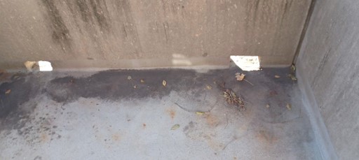
Photo No. 8 - Close up of Lookout with Drainage Scuppers.

Photo No. 9 - View looking east from north elevated sidewalk.

Photo No. 10 - View looking at northwest corner of elevated walkway.

Photo No. 11 - Existing west stair for courtyard "B".

Photo No. 12 - View of existing bathroom typical 1 bedroom apartment.

Photo No. 13 - Condition of Existing Stairs

Photo No. 14 - View of underside of elevated prestressed concrete walkway condition.

Photo No. 15 - Close up view of Corbel and Lookouts in the background.

Photo No. 16 - View of existing storm drain roof leader through elevated walkway.

Photo No. 17 - View of existing reinforced concrete "T" post and condition of elevated walkway.

Photo No. 18 - View of double corbel at south east corner of elevated walkway.

Photo No. 19 - A view looking northeast at east elevated walkway.

Photo No. 20 - View looking northeast of courtyard "B".

Photo No. 21 - View corbel to remove and install new HWW column between doors.

Photo No. 22 - View of typical walkway.

Photo No. 23 - A view looking down at east stairs.

Photo No. 24 - View of elevated walkway from landing of west stairs.

Photo No. 25 - View of existing precast lookout with shear walls.

Photo No. 26 - Close up of existing railing, elevated walkway and precast lookout shear walls.

Photo No. 27 - Courtyard "B" looking north.
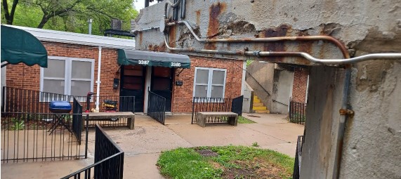
Photo No. 28 - View of existing lighting, electrical and conduit to temporary support and re-support with new steel structure.
Courtyard "C"

Photo No. 1 - View looking north from Courtyard "C".

Photo No. 2 - Looking down from edge of railing at south east stair.

Photo No. 3 - View looking at east elevated walkway.

Photo No. 4 - View of South Railing and Stairway

Photo No. 5 - View looking west from east elevated walkway.
Photo No. 6 - A view looking north at east elevated walkway.

Photo No. 7 - Overall view of all three precast outlooks.

Photo No. 8 - View of northeast edge of elevated walkway.

Photo No. 9 - View looking down Northeast stairway.

Photo No. 10 - View looking west at north elevated walkway.

Photo No. 11 - View looking southeast from northeast corner of elevated walkway.

Photo No. 12 - View looking south at courtyard "C".

Photo. No. 13 - View of underside of elevated east walkway.

Photo No. 14 - View of Northeast corner of elevated walkway.

Photo No. 15 - View looking under the covered walkway.

Photo No. 16 - View under covered walkway looking southeast and corbel to remove.

Photo No. 17 - Condition of prestressed concrete underside of covered way.

Photo No. 18 - Existing corbel and t post to remove.

Photo No. 19 - Existing corbel between apartment doors to remove.

Photo No. 20 - Existing view of northeast corner with corbel and t post to remove as well as relocated storm drainage.
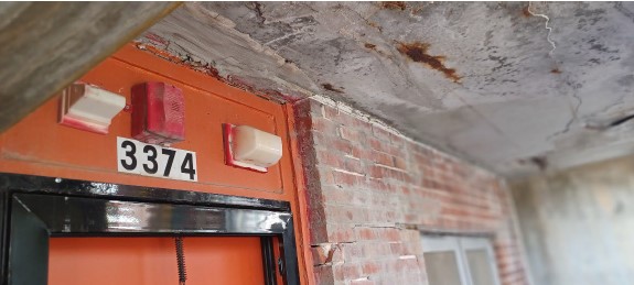
Photo No. 21 - Existing lighting nurse call and fire alarm devices to remove and cap.

Photo No. 22 - View looking east at courtyard "C".

Photo No. 23 - View looking northeast from the southeast.

Photo No. 24 - View looking south.
Courtyard "D"

Photo No. 1 - View of Courtyard "D" Stairs

Photo No. 2 - Existing typical area of refuge.

Photo No. 3 - View looking south at elevated walkway.

Photo No. 4 - View looking east at northeast corner of courtyard "D".

Photo No. 5 - View of existing northeast elevated entry way.

Photo No. 6 - Overall view looking east from courtyard "D".

Photo No. 7 - View of underside of south elevated entry way.

Photo No. 8 - View looking northeast at overall courtyard "D".
Courtyard "G"

Photo No. 1 - View looking east at south elevated walkway.

Photo No. 2 - View looking north at east elevated walkway and lookout.

Photo No. 3 - View looking down at south stairs.

Photo No. 4 - View looking northeast at prestress concrete condition by lookout.
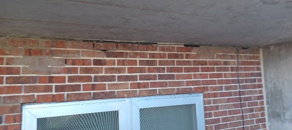
Photo No. 5 - View of brick veneer masonry to replace and repoint with shear crack.
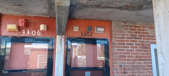
Photo No. 6 - View of existing lighting, fire alarm and nurse call to remove and cap.
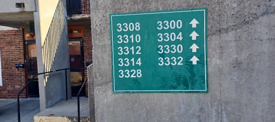
Photo No. 7 - Typical signage to remove prior to power washing and sealing then reinstall.

Photo No. 8 - View of existing stair way and landing.

Photo No. 9 - View of existing concrete to repair and patch.

Photo No. 10 - View of existing corbel to sawcut and remove.

Photo No. 11 - View of Existing retaining wall to sawcut for new bearing cap and elevated composite steel and concrete elevated walkway.

Photo No. 12 - Close up of lookout shear wall angle and decking construction for renovation.

Photo No. 13 - View of existing stairway and landing.

